


71
Service Manual
båÖäáëÜ
5. For
"Steps"
, select the 100value.
6. Choose the button for
"Technique "
until the affected motor is fully
extended.
7. Switch off the milling unit at the main switch and remove the mains
plug from the socket.
Do not press the On/Off switch, since the unit would then move to the
home position.
8. Remove the side covers, see "Removing/Replacing the Covers"
[ → 56].
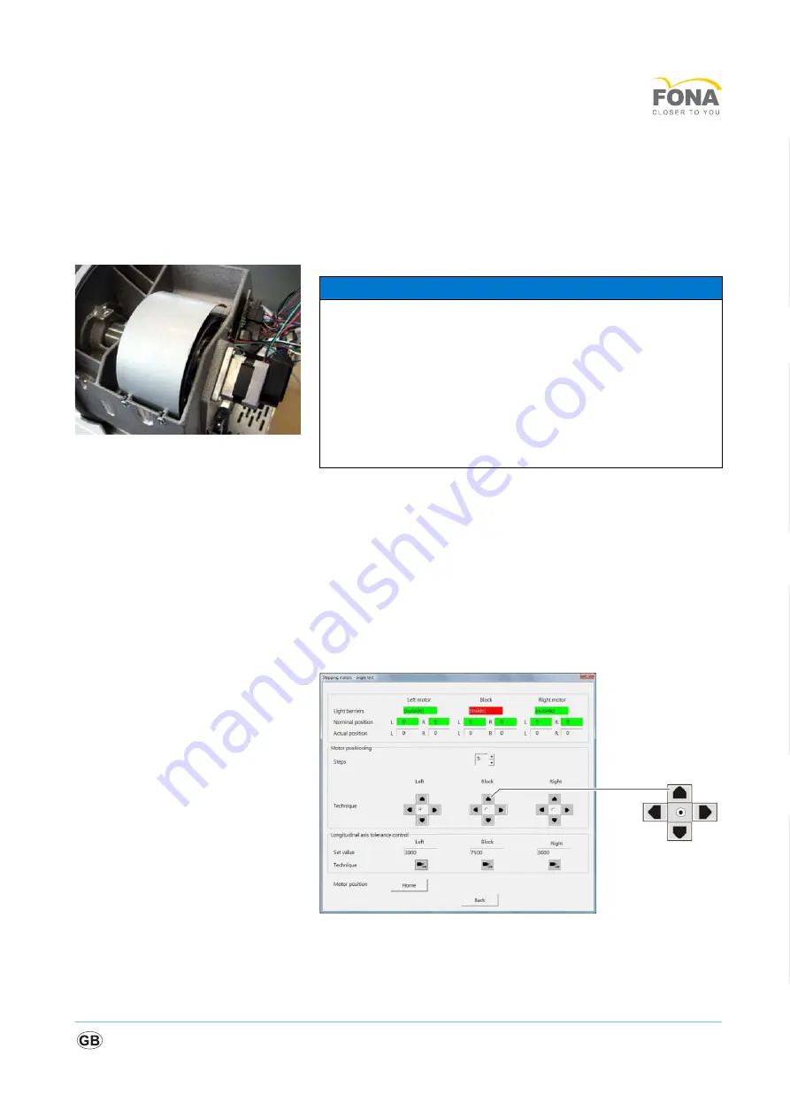
4.5.3.1.2
Preparing the block step motor
Preparing the unit
1. Switch the milling unit on.
2. Remove the block and instruments.
3. Start the Service software.
4. In the
"Test selection"
window, select the
"Stepping motors - single
step"
function.
5. For
"Steps"
, select the 100value.
6. Choose the button for
"Technique "
until the stepping motor is fully
extended.
NOTICE
If the motor is defective
If you cannot move the motor using the service software, you will have
to manually push the gear wheel outwards.
➢ Remove the side covers, see "Removing/Replacing the Covers"
[ → 56].
➢ Undo the two screws from the protecting cover and remove the
protecting cover.
➢ Manually push the gear wheel with the motor outwards until it
reaches a stop.
Содержание MyCrown Mill
Страница 1: ...j j p j b Service Manual...
Страница 15: ...15 Service Manual b Example Total test Total test...
Страница 33: ...33 Service Manual b 3 1 Force measurement errors...
Страница 34: ...34 MyCrown Mill 3 2 Stepping motor does not move...
Страница 35: ...35 Service Manual b 3 3 Spindle motor does not lock...
Страница 36: ...36 MyCrown Mill 3 4 Milling chamber door switch...
Страница 37: ...37 Service Manual b 3 5 Unit switches off Continued on next page...
Страница 38: ...38 MyCrown Mill Continued from previous page...
Страница 39: ...39 Service Manual b 3 6 Edges break off holes or wide stripes in restoration Continued on next page...
Страница 40: ...40 MyCrown Mill Continued from previous page...
Страница 41: ...41 Service Manual b 3 7 Insufficient air pressure...
Страница 42: ...42 MyCrown Mill 3 8 Stepping motor cannot be controlled...
Страница 43: ...43 Service Manual b 3 9 Faulty water pressure...
Страница 44: ...44 MyCrown Mill Continued from previous page...
Страница 45: ...45 Service Manual b 3 10 Unit cannot find starting position...
Страница 46: ...46 MyCrown Mill 3 11 Unit cannot be turned on...
Страница 47: ...47 Service Manual b 3 12 Touch errors...
Страница 48: ...48 MyCrown Mill 3 13 Service life of the milling and grinding machine is too short...
Страница 49: ...49 Service Manual b 3 14 Milling unit not addressable...
Страница 50: ...50 MyCrown Mill 3 15 LAN communication problems Continued on next page...
Страница 51: ...51 Service Manual b Continued from previous page...
Страница 52: ...52 MyCrown Mill 3 16 WLAN connection occasionally interrupted...
Страница 53: ...53 Service Manual b 3 17 WLAN communication problems...
Страница 67: ...67 Service Manual b 4 5 Replacing stepping motors Overview of stepping motors...


