IJ PUMP OPERATION AND MAINTENANCE MANUAL
3-13
BO2660-01
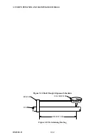
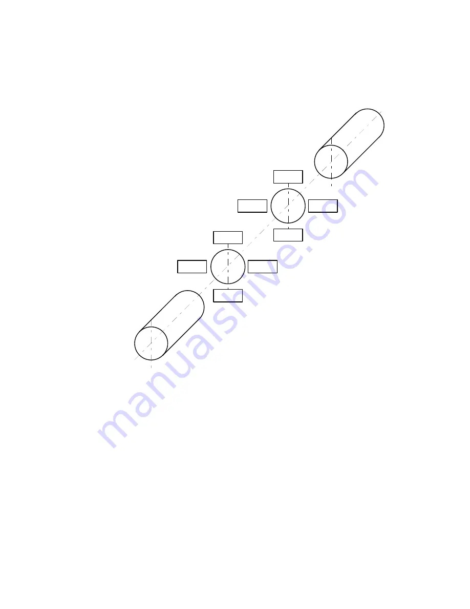
NOTE
All indicator readings must be taken on the periphery or rim
of the coupling hub or shaft, and recorded as viewed from
the fixed unit (see ALIGNMENT ORIENTATION figure).
FIXED UNIT
3
12
3
6
9
1
2
4
3
12
3
6
9
1
2
4
MOVABLE UNIT
Figure 3-12 Alignment Orientation
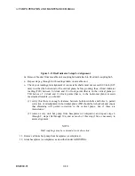
f. Attach bracket to the movable unit coupling hub or shaft. (see DIAL INDICATOR
SETUP FOR ALIGNMENT figure) Take the readings on the fixed unit coupling hub or
shaft.
g. Set the bar sag amount determined in steps a through e above into the indicator as a plus
amount (example: an indicated -0.003 would be set in as a +0.003) while in the upright
(12 o'clock) position.
h. Rotate both shafts 180° (to the 6 o'clock position) and record indicator reading.
i. Repeat steps g and h to verify accuracy.
j. Set the bracket to the horizontal (9 o'clock) position and set indicator to "0". Bar sag is
not applicable in the horizontal position.
k. Rotate both shafts 180° (to the 3 o'clock position) and record indicator reading.
l. Repeat steps j and k to verify accuracy.
Содержание IJ
Страница 2: ...IJ PUMP INSTALLATION OPERATION MAINTENANCE ...
Страница 3: ......
Страница 5: ...IJ PUMP OPERATION AND MAINTENANCE MANUAL BO2660 01 iv ...
Страница 11: ...IJ PUMP OPERATION AND MAINTENANCE MANUAL BO2660 01 x ...
Страница 13: ...IJ PUMP OPERATION AND MAINTENANCE MANUAL BO2660 01 xii ...
Страница 17: ...IJ PUMP OPERATION AND MAINTENANCE MANUAL BO2660 01 xvi ...
Страница 25: ......
Страница 35: ...IJ PUMP OPERATION AND MAINTENANCE MANUAL BO2660 01 2 10 Figure 2 1 Foundation Bolt ...
Страница 65: ......
Страница 79: ......
Страница 83: ......


