IJ PUMP OPERATION AND MAINTENANCE MANUAL
1-1
BO2660-01
1. DESCRIPTION
This section describes the principal physical features and explains the operating principles of your
multistage barrel pump, as manufactured by Flowserve Company. For an illustrative description of
the physical features of your pump, see Flowserve Product Engineering drawings in the back of this
manual; these drawings define your as built/as shipped pump. Although this section includes some
description of equipment that is purchased from a vendor and furnished with the pump (notably the
mechanical seal) as a rule, each vendor presents his own descriptive information, engineering
drawings, installation instructions, etc., when it is necessary to familiarize operating and maintenance
personnel with the particulars of his equipment (see the APPENDIX).
1.1 PHYSICAL DESCRIPTION
The following discussions concern physical features of the pump.
1.1.1 GENERAL FEATURES
The cylindrical or barrel-like case of your barrel pump is centerline-mounted. The case houses a
unitized internal assembly comprised of a rotor (essentially, a shaft with equally spaced impellers and
a pressure reducing sleeve) and stationary inner casings: intermediate diffuser-covers around each
radial impeller, a suction spacer at the first stage of the pump and a diffuser-spacer at the discharge
stage of the pump. An assembly rail that fits across each casing holds them together for removal and
installation of the internal assembly. A guide in the case receives the rail; rail and guide, together,
keep the inner casings from rotating. There is a removable head on the discharge or outboard end of
the pump case. And there is a removable seal housing in the head and the inboard end of the case. A
seal unit is attached to, or set in, each seal housing. Outside and at each end of the case, a bearing
supports the radial load of the shaft. In the same housing with the outboard radial bearing, there is a
thrust bearing that takes the axial load of the rotor. (Lubricating oil for bearings must satisfy specific
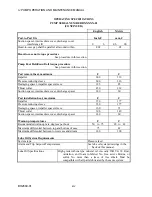
requirements; see OPERATING SPECIFICATIONS.)
1.1.1.1 Intermediate Cover-Diffuser
The diffuser is an integral part of the intermediate cover, being welded to, or formed in, the cover.
This is necessary to prevent the diffuser from rotating. Moreover, a diffuser that is welded to the
intermediate cover is considered by Flowserve to be inseparable outside the factory.
1.1.1.2 Suction Spacer and Discharge Diffuser-Spacer
The suction spacer does not incorporate a diffuser. The discharge spacer does incorporate a diffuser in
the same manner as the intermediate cover (see Intermediate Cover-Diffuser above).
1.1.1.3 Wearing Rings and Bushings
A renewable wearing ring is fixed in each intermediate diffuser-cover, the suction spacer, and the
discharge diffuser-spacer. A renewable bushing is fixed in each intermediate diffuser-cover and the
discharge diffuser-spacer. In a double suction pump, the suction spacer also incorporates a bushing.
These rings and bushings protect the covers and spacers from the washing action that is generated by
the skirt and hub of each impeller as they spin rapidly in the pumpage (or flow). The rings and
bushings are surface-hardened.
Содержание IJ
Страница 2: ...IJ PUMP INSTALLATION OPERATION MAINTENANCE ...
Страница 3: ......
Страница 5: ...IJ PUMP OPERATION AND MAINTENANCE MANUAL BO2660 01 iv ...
Страница 11: ...IJ PUMP OPERATION AND MAINTENANCE MANUAL BO2660 01 x ...
Страница 13: ...IJ PUMP OPERATION AND MAINTENANCE MANUAL BO2660 01 xii ...
Страница 17: ...IJ PUMP OPERATION AND MAINTENANCE MANUAL BO2660 01 xvi ...
Страница 25: ......
Страница 35: ...IJ PUMP OPERATION AND MAINTENANCE MANUAL BO2660 01 2 10 Figure 2 1 Foundation Bolt ...
Страница 65: ......
Страница 79: ......
Страница 83: ......


