IJ PUMP OPERATION AND MAINTENANCE MANUAL
BO2660-01 3-14
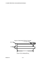
Figure 3-13 Dial Indicator Setup For Alignment
m. Remove bracket from movable unit coupling hub and attach to fixed unit coupling hub.
n. Repeat steps g through l with readings taken on movable unit.
o. Check your readings; misalignment of connectable shafts must not exceed 0.01 inch (0.25
mm) in either the horizontal or the vertical plane, before grouting; thus, if total indicator
reading (TIR) between 6 o'clock and 12 o'clock points (that is, in the vertical plane) or
TIR between 3 o'clock and 9 o'clock points (that is, in the horizontal plane) exceeds
maximum allowable, you should:
(1) verify that there is enough clearance between holddown bolts and holes to permit
correction of misalignment in horizontal plane (TIR should be rechecked) and ensure
that shimming will permit correction in the vertical plane; but, if these are
inconclusive:
(2) remove every unit but pump from baseplates (or soleplates) and repeat steps 6
through 8, steps 10a through 10n, and as much of this step (10o) as necessary to
assure alignment.
NOTE
Half couplings may be removed at your discretion.
11. Remove all units but pump from baseplates (or soleplates).
12. Grout baseplates (or soleplates) as described under GROUTING.
Содержание IJ
Страница 2: ...IJ PUMP INSTALLATION OPERATION MAINTENANCE ...
Страница 3: ......
Страница 5: ...IJ PUMP OPERATION AND MAINTENANCE MANUAL BO2660 01 iv ...
Страница 11: ...IJ PUMP OPERATION AND MAINTENANCE MANUAL BO2660 01 x ...
Страница 13: ...IJ PUMP OPERATION AND MAINTENANCE MANUAL BO2660 01 xii ...
Страница 17: ...IJ PUMP OPERATION AND MAINTENANCE MANUAL BO2660 01 xvi ...
Страница 25: ......
Страница 35: ...IJ PUMP OPERATION AND MAINTENANCE MANUAL BO2660 01 2 10 Figure 2 1 Foundation Bolt ...
Страница 65: ......
Страница 79: ......
Страница 83: ......

