IJ PUMP OPERATION AND MAINTENANCE MANUAL
3-11
BO2660-01
6. Using optical alignment equipment (see TOOLS AND EQUIPMENT above), align centerline
of every baseplate (or pair of soleplates) within 0.015 inch (0.38 mm) of a common centerline
(see BASEPLATE AND SOLEPLATES IN TRAIN and MULTIPLE BASEPLATES IN
TRAIN figures).
7. Level and anchor every baseplate (or pair of soleplates) in train, according to instructions that
are applicable to your circumstance:
a. First method (using optical alignment equipment (see step 6), level baseplate (or
soleplates) on shims or leveling screws (see step 2)) within nominal leveling gradient of
0.001 inch per 12 inches (0.03 mm per 305 mm). Then tighten down anchor nuts and
recheck for nominal gradient. If baseplate (or soleplates) is not level, loosen anchor nuts,
relevel it, retighten nuts, and recheck for nominal gradient. Continue this process until the
baseplate (or soleplates) is anchored and level.
b. Second method (using precision machinist level)
(1) level a multi-pad baseplate as instructed by steps 7b (1) through 7b (4) under ONE
BASEPLATE FOR ENTIRE TRAIN OF UNITS above,
(2) level soleplates as described under LEVELING SOLEPLATES below, and
(3) level a baseplate that supports only the pump, or a single unit, as described under
BASEPLATE FOR PUMP OR SINGLE UNIT below.
8. Set units (that is, driver, pump, etc.) in place on baseplates (or soleplates) and loosely install
enough holddown bolts in each unit to ensure that all holes in units and baseplates (or
soleplates) line up.
9. Install half-couplings on shafts.
NOTE
Check hubs for run out or possible bent shaft conditions
before attempting alignment of units.
10. Check alignment of all connectable shafts as described by the following steps. Where there is
a turbine, start with turbine and pump shafts; otherwise, start with high-speed pump and
adjacent driving unit; then complete schedules for other connectable shafts as shown in
SHAFT ROUGH ALIGNMENT SCHEDULES figure.
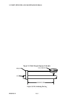
a. Determine the distance from the bracket mounting point to the indicator reading point.
b. Securely attach the bracket to a length of rigid pipe, and install the indicator at the
distance determined in step a above. (See DETERMINING BAR SAG figure)
c. Hold the pipe with the indicator facing up and set at "O". Without touching bracket,
rotate the pipe 180 so that the indicator is facing down. Read the indicator and record the
reading. This is the amount of bar sag.
d. Rotate the pipe again so that indicator is facing up. It must return to "O".
e. Repeat steps c and d to confirm reading.
Содержание IJ
Страница 2: ...IJ PUMP INSTALLATION OPERATION MAINTENANCE ...
Страница 3: ......
Страница 5: ...IJ PUMP OPERATION AND MAINTENANCE MANUAL BO2660 01 iv ...
Страница 11: ...IJ PUMP OPERATION AND MAINTENANCE MANUAL BO2660 01 x ...
Страница 13: ...IJ PUMP OPERATION AND MAINTENANCE MANUAL BO2660 01 xii ...
Страница 17: ...IJ PUMP OPERATION AND MAINTENANCE MANUAL BO2660 01 xvi ...
Страница 25: ......
Страница 35: ...IJ PUMP OPERATION AND MAINTENANCE MANUAL BO2660 01 2 10 Figure 2 1 Foundation Bolt ...
Страница 65: ......
Страница 79: ......
Страница 83: ......

