background image

4-22


I

NSTALLING


ALINTE

4

PAGE

 E

QUIPMENT


AND

 S

OFTWARE

3.

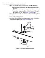
Mate the autoloader to the engine adaptor assembly as follows:

A

)

Locate the two adaptor plate pins inside the two autoloader 
keyholes.

B

)

Raise the autoloader feet gradually (using a 8 mm spanner) so 
that the 

two

 adaptor assembly pins are 

touching

 the bottom 

lip of the keyhole slot, see 

Figure 4.19 on page 4-23

.

4.

Check that the autoloader is level using a spirit level on the top frame 
cover.

5.

Lock the four autoloader feet. 

6.

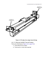
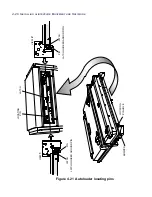
Using the previously removed 5-0ff M5 screws, fix the autoloader to 
the adaptor assembly, see 

Figure 4.19 on page 4-23

.


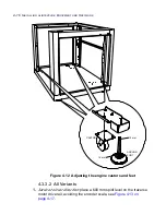
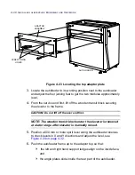
Figure 4.18  Adjust the autoloader feet

8 mm

LOCKING

NUT

JACK

BOLT

SEATING

PLATE

Содержание alinte4page

Страница 1: ......

Страница 2: ...hoto Film Co Ltd that may be registered in certain jurisdictions Luxel Celix FineScan Celsis C dot C Scan Quattro Lanovia ColourKit and Celebrant are trademarks of FUJIFILM Corporation that may be reg...

Страница 3: ...ntial environment may result in interference to other equipment in which case the user will be required to correct the interference at their own expense In some coun tries this equipment may be subjec...

Страница 4: ...utomatic alinte4page Manual Semi Automatic and Fully Automatic Single Cassette SAL with and without manual load slot MLS alinte4page Fully Automatic with Multi Cassette Autoloader MAL Engineers are re...

Страница 5: ...der 1 7 Network Connections 1 9 Loading Applications and Options 1 10 Completing the Installation Report 1 10 Chapter 2 Safety on the alinte4page Health and Safety at Work 2 1 Warnings and Cautions 2...

Страница 6: ...16 Acoustic Noise Safety 2 16 Safety Interlock System 2 16 Interlocked Covers 2 17 Locked Covers 2 19 Interlock Over rides 2 20 Laser Safety 2 21 Laser Precautions 2 22 Laser Safety Shutter 2 22 Lase...

Страница 7: ...l 4 5 Remove Entry Level Engine Top Cover Semi Auto 4 6 Heavy Lifting Operations 4 6 Installation Sequence 4 7 Semi Automatic alinte4page entry level 4 7 Semi Automatic alinte4page 4 7 Alinte4page SAL...

Страница 8: ...Remove Transit Fixings Using the Brake Override 4 37 Set up the Brake Override 4 38 Lower the Elevator 4 40 Raise the Elevator 4 40 Remove the Brake Override 4 40 Remove the Transit Fixings 4 40 Inte...

Страница 9: ...te4page Sys tem Start to Commission the Platesetter 5 1 Initial Software Checks and Setups 5 2 Open Main Diagnostics and Check Engine Clock 5 2 Check Power Supply Voltages 5 3 Check Cover Interlocks 5...

Страница 10: ...ut with a Punch 5 25 Punch Configuration Check 5 25 Check Image to Top of Plate Accuracy 5 27 Check Image to Punch Crop Accuracy 5 28 Check Image Base Position in RIP 5 29 Check for Image Centering 5...

Страница 11: ...r Maintenance 6 3 Emptying the Chad Tray with Punch 6 3 Emptying the Interleaf Bin SAL MAL 6 3 Cleaning the Spinner Mirror 6 3 Checking the Platesetter Environment 6 3 Vacuum Clean the Platesetter 6 4...

Страница 12: ...PRELIMINARIES...

Страница 13: ...4page Entry Level Manual and Semi Automatic on page 1 2 Alinte4page Manual system See Alinte4page Manual on page 1 3 Alinte4pageSemi Automatic system See Alinte4page Semi Automatic on page 1 4 Alinte4...

Страница 14: ...r representative for all site require ments described in the Alinte4page Pre Installation Guide 1 1 1 Alinte4page Entry Level Manual and Semi Automatic A typical Entry Level Manual platesetter is illu...

Страница 15: ...brant Gateway Rampage PCI Dashboard application see Installation Notes with PCI software 1 1 2 Alinte4page Manual A typical alinte4page manual platesetter system is illustrated in Figure 1 2 on page 1...

Страница 16: ...t Gateway Rampage PCI Dashboard application see Installation Notes with PCI software 1 1 3 Alinte4page Semi Automatic A typical alinte4page semi automatic system is illustrated in Figure 1 3 on page 1...

Страница 17: ...ied separately by the customer RIP application software with options of Celebrant Gateway Rampage PCI Dashboard application see Installation Notes with PCI software CD 1 1 4 Alinte4page Single Cassett...

Страница 18: ...ngine Autoloader with MLS option Trolley with cassette one trolley supplied as standard with the option ofup to five PAT Air Filter external manufacturer supply Vacuum pump Processor external manufact...

Страница 19: ...ftware with options of Celebrant Gateway Rampage PCI application see Installation Notes with PCI software CD 1 1 5 Alinte4page Multi Cassette MAL Autoloader A typical multi cassette autoloader alinte4...

Страница 20: ...ied as standard with the option of up to seven cassettes The standard trolley has a fixed platen An optional tilt trolley has an adustable platen to allow passage through narrow doorways PAT Air Filte...

Страница 21: ...on 1 Ethernet or any suitable network from the RIP PC to DTP sys tems see documentation supplied with network equipment 2 FireWire link IEEE 1394 between the Engine and the RIP PCI PCI RIP PC ETHERNET...

Страница 22: ...irmware A set of backup CDs holding the installed firmware also contain useful Release Notes with required NVRAM data for different machine configurations 2 Desktop this software is loaded on the RIP...

Страница 23: ...safe working practices which must be strictly observed at all times This chapter explains the safety conventions used in this manual and highlights safety practices specific to the product 2 To ensur...

Страница 24: ...clothing or jewellery which could be hazardous when in contact with any part of the equipment or which could reflect laser light into the eyes 2 1 3 Equipment and Tools Use the approved service tools...

Страница 25: ...60950 1 Product Model No Serial No Volts Max Current Manufactured 50 60Hz FFEI Ltd HEMEL HEMPSTEAD ENGLAND This laser conforms to the applicable requirements of 21 CFR Sub chapter J CLASS 1 LASER LAS...

Страница 26: ...trates the laser and spinner risks to the engineer on the user side after the cover is removed and the inter locks are defeated Figure 2 2 Drum moving parts and edge detect warning labels LASER RADIAT...

Страница 27: ...der Warning Labels Figure 2 3 on page 2 5 shows a moving parts label on the PTM feed head Figure 2 3 Plate feed moving parts 2 2 4 Autofeeder Warning Labels Figure 2 4 on page 2 6 to Figure 2 7 on pag...

Страница 28: ...2 6 SAFETY ON THE ALINTE4PAGE Figure 2 4 Autofeeder elevator motor warning labels WARNING ENSURE MAINS SUPPLY DISCONNECTED BEFORE SERVICING...

Страница 29: ...ALINTE4PAGE INSTALLATION GUIDE 2 7 Figure 2 5 Autofeeder elevator warning label...

Страница 30: ...2 8 SAFETY ON THE ALINTE4PAGE Figure 2 6 Autofeeder elevator moving parts warning labels USER SIDE SERVICE SIDE...

Страница 31: ...N GUIDE 2 9 Figure 2 7 Autofeeder earth wire safety label 2 2 5 Optics Warning Labels Figure 2 8 on page 2 10 shows the areas of risk for the engineer from exposed laser beams when the optics base lid...

Страница 32: ...0 SAFETY ON THE ALINTE4PAGE Figure 2 8 Optics base laser warning labels 2 2 6 Electrical Warning Labels Figure 2 9 on page 2 11 shows the area of risk from high tension volt age inside the interlock b...

Страница 33: ...ing Labels Figure 2 10 on page 2 12 entry level and Figure 2 11 on page 2 13 shows the areas of laser beam risk to the engineer when the inter locked covers are opened and the interlocks are defeated...

Страница 34: ...2 12 SAFETY ON THE ALINTE4PAGE Figure 2 10 Interlock defeated warning labels typical alinte4page entry level...

Страница 35: ...ALINTE4PAGE INSTALLATION GUIDE 2 13 Figure 2 11 Interlock defeated warning labels typical alinte4page manual...

Страница 36: ...negate or bypass any of the above safety devices 2 2 9 Unattended Equipment Never leave equipment unattended unless in a safe condition with respect to the following hazards Electrical Mechanical Lase...

Страница 37: ...lock equipment access covers to prevent internal access on the service side of the engine and autoloader The platesetter consists of assemblies that are excessively heavy for one engineer to lift If...

Страница 38: ...er mirror presents a danger for the engineer NOTE Note that even when rotating at an idle speed the spinner can appear in a halt state WARNING The spinner rotates at very high speeds and can cause ser...

Страница 39: ...ge 2 19 alinte4page SAL show the location of the interlocked covers WARNING If the platesetter has to be run with a cover open and the interlocks over ridden extreme care must be taken to avoid the fo...

Страница 40: ...2 18 SAFETY ON THE ALINTE4PAGE Figure 2 13 Location of interlock covers alinte4page SAL 2 1...

Страница 41: ...the over ridden state The Laser Safety Officer must be informed when the machine is in this state 2 3 2 Locked Covers All screw locked covers are shown in Figure 4 2 on Page 4 4 After completing the...

Страница 42: ...nto the interlock switch shown in Figure 2 15 on page 2 20 engine and Figure 2 16 on page 2 21 autoloader Operating an over ridden system allows the platesetter to generate a laser beam rotate the spi...

Страница 43: ...r performance of proce dures other than those specified in this manual may result in hazard ous radiation exposure The alinte4page CTP is labelled as a Class I laser product when all the covers are cl...

Страница 44: ...e general area Remove the protective lid of the optics base only in accordance with the instructions given in the service procedure Wear attenuating laser safety goggles where there is a risk of direc...

Страница 45: ...light Note the following laser radiation warning WARNING Never look directly into a laser beam This could cause seri ous damage and possible blindness When working on a Class IIIB laser source always...

Страница 46: ...a room a curtained area or a purpose built DLA tent 2 4 3 1 A DLA Room All other personnel should be warned of the hazard by A laser warning notice attached to the door s leading to the room An examp...

Страница 47: ...25 Figure 2 18 Typical laser warning signs NO ENTRY TO UNAUTHORISED PERSONNEL WHEN WARNING LIGHT IS ON LASER CLASS 3B OPERATIONS NO ENTRY TO UNAUTHORISED PERSONNEL WHEN WARNING LIGHT IS ON LASER CLAS...

Страница 48: ...2 26 SAFETY ON THE ALINTE4PAGE...

Страница 49: ...eficiencies must be reported immediately Depending on the ordered alinte4page configuration a typical con signment comprises a set of boxes containing the following items Engine all variants Autoloade...

Страница 50: ...ed to the outside of the box and the engine itself The following steps are taken when there has been damage corrosion or positive Tip or Drop indications see Figure 3 1 on page 3 3 below 1 Record the...

Страница 51: ...he outside of the box A typical unpacking method for a FFEI module is as follows 1 Locate the box in a position where there is enough room to unpack and fork lift the module from its box 2 Cut any ban...

Страница 52: ...lly cut away the vacuum seal wrapping and remove any bubble wrap 7 Remove the front block of the wooden frame to the palette see Figure 3 2 on page 3 4 before lifting the unit Figure 3 2 Unpacking FFE...

Страница 53: ...cate the Accessories packs and check that the items in Table 3 1 on page 3 5 are shipped 12 Arrange locally for the removal of disposable packaging materials The box cardboard and foam are all recycla...

Страница 54: ...particularly when lifting into position during an installation Any pressure on the front or rear or any torsional stress created by lifting a unit from the wrong points can alter mechanical alignment...

Страница 55: ...nd transporting the mod ules whenever possible It must possess undistorted forks that can lift the weight of the module evenly They should be at least 1100 mm 43 in long and have a distance apart of b...

Страница 56: ...3 8 UNPACKING AND HANDLING...

Страница 57: ...4 This chapter shows how to install and connect the alinte4page plateset ter equipment for a manual and semi automatic system Start the Installation 4 1 Install the Processor 4 9 Install the Engine 4...

Страница 58: ...rked ON and OFF 4 1 2 1 Check Floor Gradient While the machine is not yet in position you may need to check that the rise fall floor gradient for the platesetter area is within the values shown in Fig...

Страница 59: ...the platesetter floor level is uneven then check for a more suitable area nearby 5 If the floor level gradient is within specification then start the installation using the recommended sequence This...

Страница 60: ...ion in order to access assemblies Where possible refit them to protect the interior from dust contamination Note the fol lowing Screw locked SL doors are fixed into position using posidrive SL NL I SL...

Страница 61: ...ss 4 1 3 1 Remove Engine Top Cover The top cover on the Manual SAL MAL engine is removed as follows 1 Open the user door and remove the 2 off posi screws shown in Figure 4 3 on page 4 5 2 Lift the cov...

Страница 62: ...1 Open the user door and remove the 1 off posi screw The other side is held by a pin 2 Lift the cover towards the output to release it from below the load platen Figure 4 4 Remove the engine top cove...

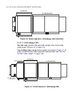
Страница 63: ...4 1 5 1 Semi Automatic alinte4page entry level Install a semi automatic system in the the following module order Figure 4 5 on page 4 7 below Figure 4 5 Install sequence alinte4page entry level semi...

Страница 64: ...atic system in the the module order shown in Figure 4 7 on page 4 8 Two or More SALs install the first system as shown in Figure 4 7 on page 4 8 and then the other systems in reverse order see Set the...

Страница 65: ...nit 1 Locate the processor in its correct working position 2 Set the processor plate entry slot height to 1 012 mm 39 84 in to match the output of the Engine see Figure 4 11 on page 4 15 3 Level the p...

Страница 66: ...ball cage is very delicate and easily damaged Take care when unpacking this assembly 2 Check that the ball cage is clean and undamaged Lay the cage on a flat surface and check that it is straight if i...

Страница 67: ...ALINTE4PAGE INSTALLATION GUIDE 4 11 Figure 4 9 Removing the traverse transit bolt TRANSIT BRACKET SCREW FIXING POINTS SCREW FIXING POINT ORANGE TRANSIT SCREW...

Страница 68: ...oosen the 2 off screws on the traverse transit bracket left hand side of carriage see Figure 4 9 on page 4 11 while supporting the traverse carriage by hand from the motor casting 7 Remove the lower s...

Страница 69: ...om of the rule is 1 012 mm from the floor Make sure the input rollers and tank frame are level in both planes NOTE Do not use the engine panels for levelling 5 Re adjust the feet if necessary while ma...

Страница 70: ...and re adjust the processor Adjust the appropriate corners upwards to obtain improved levelling using 12 mm and 16 mm spanners See Figure 4 12 on page 4 16 See Level the Engine on page 4 15 for more...

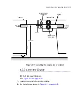
Страница 71: ...sor 4 3 3 Level the Engine 4 3 3 1 Manual System See Figure 4 12 on page 4 16 1 Locate the engine in its working position 2 Set the height as shown in Figure 4 11 on page 4 15 RULER PLASTIC INPUT ROLL...

Страница 72: ...E Figure 4 12 Adjusting the engine castors and feet 4 3 3 2 All Variants 1 Service to User direction place a 600 mm spirit level on the traverse motor drive rail avoiding the encoder scale see Figure...

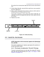
Страница 73: ...r instance check the level again after 24 hours for any signs of anchor feet sinking 4 Replace any covers Figure 4 13 Vertical levelling 4 4 Install the Autoloader NOTE Information in this section onl...

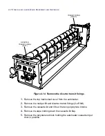
Страница 74: ...om the autoloader 2 Remove the nudger lift and diverter transit fixings 2 off M4 3 Remove the cassette lid and lift out the two polystyrene blocks 4 Remove the tape holding down the cassette lid flap...

Страница 75: ...the nudger transit fixings 4 4 1 1 Remove the MLS Transit Fixings Remove the following see Figure 4 16 on page 4 20 A Tape holding the door closed B Transit screw on the M roller assembly NUDGER LIFT...

Страница 76: ...4 20 INSTALLING ALINTE4PAGE EQUIPMENT AND SOFTWARE Figure 4 16 MLS transit screw TRANSIT SCREW M ROLLER ASSEMBLY MLS COVER TAPE BOTH ENDS NUDGER FRAME NUDGER TRANSIT FIXING NUDGER ARM...

Страница 77: ...nsure full operator safety when the auoloader top cover is removed 2 V6A_CAN_AUTO from MSB3 SK1 to MSB2 SK3 This cable is in the Accessories pack 3 V6A_MSB3_PWR from MSB3 PL31 to MSB3_PWR connector on...

Страница 78: ...spanner so that the two adaptor assembly pins are touching the bottom lip of the keyhole slot see Figure 4 19 on page 4 23 4 Check that the autoloader is level using a spirit level on the top frame c...

Страница 79: ...DE 4 23 Figure 4 19 Locate the adaptor pins and keyhole slots M5 SCREW 5 OFF ADAPTOR ASSEMBLY FITTED TO ENGINE AUTOLOADER ADAPTOR PLATE PIN 2 OFF KEYHOLE 2 OFF AUTOLOADER ADAPTOR ASSEMBLY KEYHOLE PIN...

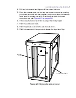
Страница 80: ...der See Figure 4 20 on page 4 25 CAUTION At this stage make sure you push the trolley into the autoloader very carefully to avoid damaging autoloader components 2 Carefully push the trolley into the a...

Страница 81: ...ou can hear the cassette latch snap to engage correctly Check that the latch is hooked around the pin see Figure 4 21 on page 4 26 6 If the cassette fails to latch then re adjust the trolley height 7...

Страница 82: ...STALLING ALINTE4PAGE EQUIPMENT AND SOFTWARE Figure 4 21 Autoloader locating pins LOCATING PIN LATCH BUMP ER LOCATING PIN HOLE LATCH PIN LATCH HOOKED AROUND PIN LATCH PIN LATCH HOOKED AROUND PIN VIEW 1...

Страница 83: ...PAGE INSTALLATION GUIDE 4 27 Figure 4 22 Adjust the trolley height LOCKNUT LOCKNUT BELOW PAD POSITION PAD WHEEL HOOD CLOCKWISE TO RAISE WHEEL TROLLEY CASTOR WHEEL 4 OFF TROLLEY BASE 1 2 CHECK LEVELS 1...

Страница 84: ...econd cassette install the second machine as follows 1 Cassette and Trolley 2 Autoloader 3 Engine 4 Processor 3 If you follow this procedure correctly you will have two correctly installed autoloaders...

Страница 85: ...eder Basic Level NOTE A basic levelling of the two units is made before the two units are correctly aligned for smooth cassette transfers A fine level check is made at the end of the alignment 1 Befor...

Страница 86: ...ION Do not lift off the user end first NOTE The wooden transit block under the elevator is removed at a later stage after elevator is manually raised 5 Position a 600 mm or more spirit level along the...

Страница 87: ...urfaces and check that it moves smoothly across in both directions see Figure 4 25 on page 4 33 8 Continue to interconnect the cable and load the software before checking the mechanical alignment of t...

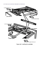
Страница 88: ...4 32 INSTALLING ALINTE4PAGE EQUIPMENT AND SOFTWARE Figure 4 24 Levelling the autofeeder CASSETTE TROLLEY CASSETTE TROLLEY AUTOLOADER ENGINE AUTOLOADER ENGINE AUTOFEEDER AUTOFEEDER...

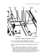
Страница 89: ...eeder V6AF_Mains_Feed 99700688 this is routed to avoid signal cables Fit the IEC connector at the rear of the Interlock box ILOCK and run along the base of the engine Make sure the cable is passed thr...

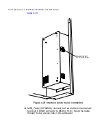
Страница 90: ...ARE page 4 34 Figure 4 26 Interlock box to mains connection MSB_Power 99700690 connect the free end from the Interlock box ILOCK MSB3 connector to MSB 4 PL31 Route the cable through the top access hol...

Страница 91: ...IDE 4 35 Figure 4 27 MSB 4 connectors PL8 PL10 PL25 PL24 PL23 PL7 PL9 PL12 PL14 PL21 PL26 PL18 PL19 SK3 SK2 PL6 PL5 SK1 PL4 PL3 PL2 PL1 PL15 PL16 PL20 PL22 PL31 PL17 PL27 PL28 PL29 PL30 PL11 PL13 LK1...

Страница 92: ...cable through the bottom access hole on the autofeeder WARNING an earth wire MUST be fitted between the autoloader and autofeeder Check for earth continuity between the two modules WARNING Make sure t...

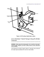
Страница 93: ...erride WARNING Keep away from moving parts on or near the scissor jack elevator while using this procedure Safety features on the autofeeder are overridden Use the brake override procedure below to ma...

Страница 94: ...the inline connector between MSB_DOOR CABLE 99700704 and DOOR_LOCK 99700683 and connect the door_lock end to the short cable extension of the brake override 3 Switch on the engine and put into Boot m...

Страница 95: ...E4PAGE INSTALLATION GUIDE 4 39 Figure 4 30 Connecting the brake over ride assembly MSB4 INVERTER PL31 PL1 PL2 MSB_PWR MSB_DOOR DOOR_LOCK BRAKE OVERRIDE ASSEMBLY SWITCH A B A B MSB_PWR CONNECT TO CONNE...

Страница 96: ...or shaft by hand to move the shelves up anti clockwise or down clockwise 2 Depress the override switch to release the brake 3 Turn the elevator motor shaft anti clockwise to tension the chain 4 5 3 4...

Страница 97: ...move the 2 off elevator side brackets 4 off screws on each side C Cassette rear remove the 1 off 2 screws cassette rear bracket during the Cassette Change procedure Figure 4 31 Removing transit fixing...

Страница 98: ...4 42 INSTALLING ALINTE4PAGE EQUIPMENT AND SOFTWARE Figure 4 32 Removing transit fixing view 2...

Страница 99: ...bottom cassette for a Change Cassette and remove the transit fixings 4 5 5 Integrate and Level the Autofeeder Fine CAUTION ALWAYS push the cassette back into the Autofeeder before switching ON the sy...

Страница 100: ...ins and note if the cassette front end has to nudge in either horizontal direction to reach the correct mount position CAUTION ALWAYS push the cassette back into the Autofeeder before switching ON the...

Страница 101: ...lign with the location pins lower the feet on the autofeeder 5 Repeat the steps above to check the alignment again until the cassette latches correctly 6 Tighten the 4 off screws on adaptor angles and...

Страница 102: ...he cassette with plates 3 Adjust the trolley feet so that the side bumpers are level with the guides shown in Figure 4 35 on page 4 48 4 Dock the trolley check that the docking light is on and push th...

Страница 103: ...ALINTE4PAGE INSTALLATION GUIDE 4 47 6 Two man lift fit the top autofeeder pod and secure into position at each corner 4 off screws in support pack 7 Refit all the covers...

Страница 104: ...4 48 INSTALLING ALINTE4PAGE EQUIPMENT AND SOFTWARE Figure 4 35 Levelling the trolley BUMPER GUIDE CASSETTE BUMPER CASSETTE BUMPER BUMPER GUIDE...

Страница 105: ...he cage is exposed 2 Pull the carriage forward holding the ball cage as required until the two assemblies are inline with the screw fixing as shown in Figure 4 36 on page 4 49 below 3 You may have to...

Страница 106: ...fitted by the customer as an option Cables B C and D listed below are fitted through the light seal entry and connected directly to the Formatter Board see Figure 4 37 on page 4 50 and Figure 4 38 on...

Страница 107: ...ternatively connect to a local laptop for installation use D RS232 Processor Comms cable to the Processor semi and fully automatic only E MAINS_IN to the local mains outlet and circuit breaker Check t...

Страница 108: ...t contamination inside the drum and optics module by generating clean filtered air Use the supplied manufacturer s Installation and Operator s Guide to obtain details on how to register the unit befor...

Страница 109: ...tch on 4 Check the following LEDs Power is ON 1 2 and 3 Filters are OFF Low flow is OFF 5 Move the unit to be next to the Engine 6 Attach the flexible duct to the PAT and run the PAT for 15 minutes to...

Страница 110: ...and Heights Inca used on this product require an earth braid to be fitted from the processor to the engine to avoid power spikes 4 6 5 1 G J Earth Cable Fitting From the engine end 1 Switch off the en...

Страница 111: ...the back of the box 7 Fit the cable to the earth stud shown in Figure 4 41 on page 4 56 b 8 Replace the processor cover Figure 4 41 Fitting the processor earth to the engine BASE EARTH STUD CABLE ENTR...

Страница 112: ...a risk that the monitor light can cause plate fogging Assess the risk with the customer and fit the supplied encapsulite G10 yellow film as follows 1 Cut out the film sheet so that it fits the monitor...

Страница 113: ...e aligned within 1 mm see Figure 4 42 on page 4 58 Figure 4 42 No Punch output alignment Punch machines check that the punch output platen is flush with the punch exit slot see Figure 4 43 on page 4 5...

Страница 114: ...Clean Engine Drum 1 If the engine doors have been opened for a lengthy period then vacuum the drum or clean it with a lintless cloth to remove dust 2 Close all covers to prevent any more dust from en...

Страница 115: ...installed at this stage Server includes the device driver Desktop includes the alinte4page dashboard 4 7 1 System Pre Requirements 1 The PC operating system must be one of the following for running t...

Страница 116: ...t using the procedure in the PCI Installation Guide 3 After loading PCI software A restart the PC B switch on the platesetter 4 7 3 Install the Server Device Drivers Device drivers are installed autom...

Страница 117: ...nline Installation Report from Installation Data 1 Select Edit and enter A Name of the customer B Start date of the installation 2 Save the Report 3 Open the Report again to display a list of licence...

Страница 118: ...llation All new hardware upgrades to an existing machine are supplied with their own Installation Manual which are downloaded from SIO New software options will normally require the local service engi...

Страница 119: ...interlock doors and covers traverse level check plate feed 5 This chapter describes how to test set up and demonstrate a manual semi auto SAL and MAL platesetter with and without a punch as a working...

Страница 120: ...d out in the recommended order described in this chapter using additional information from the User s Guide if the MMI option is fitted Service Guide RIP Documentation for the appropriate application...

Страница 121: ...r a filename for saving the captured text 5 From the Main prompt open the Diagnostics menu main diagnostics Enter password uk0 6 Check the current time and date on the Engine using service time now 7...

Страница 122: ...BROKEN Autoloader cover open Check if the following devices stop plate handling motors laser light spinner vacuum pump 3 Engine and Autoloader Replace the autoloader cover and the system reboots 4 En...

Страница 123: ...t the check after 24 hours 1 Insert the interlock override actuator key into the door interlock switch on the user side 2 Check that the spinner and traverse are disabled They are enabled if the Engin...

Страница 124: ...eet to minimise creep and obtain an improved level A small adjustment of 1 4 to 1 2 turn 0 25 to 0 5 mm on the engine feet is usually sufficient 10 Repeat steps 2 to 9 until creep is within the specif...

Страница 125: ...llowing A The plate enters the drum without damage B The interleaf sheet enters the bin autoloader only C The plate conforms without damage at the registration pins and pull bar shoes D The plate exit...

Страница 126: ...erating optics test patterns are built into the machine and are not dependent on the licenced resolutions 5 3 1 Check Beam Focus This procedure allows you to verify and change the NVRAMs for the Beam...

Страница 127: ...nvram dnv ND_RES96_RIP_EXPOSE Figure 5 3 RIP exposure settings 96 resolution 4 Navigate to the V6 Optics Setup screen optics mmi This displays the Optics Setup Screen as shown in Figure 5 4 on page 5...

Страница 128: ...lue to the 96 resolution value recorded in step 2 7 Save and exit 8 Load a large plate 9 Run the Auto focus Test main diagnostics service optics optics mmi Set the Test defaults to Y Press return then...

Страница 129: ...t is for 48 resolution Table 5 1 Beam focus check AUTO FOCUS MACRO RUN TEST STRIPS Focus 96V Focus 96H Focus 48V Set Defaults Yes N A N A Scan Start Posn mm 10 N A N A Strip Width mm 8 8 12 Start Valu...

Страница 130: ...he density at the top of each strip to find the strip with the lowest density Select the focus setting for the lowest density test strip NOTE The start value is 900 and the step value is 50 in this ex...

Страница 131: ...positions for each remaining plate thickness by calculating the offset values from Table 5 2 on page 5 13 as follows A for instance if a 96 res 0 15 plate gives 600 then a 0 30 plate gives 525 or B fo...

Страница 132: ...xposed plate 1 Measure the density at the top of each strip to find the strip with the lowest density Select the focus setting for the lowest density test strip NOTE The start value is 2500 and the st...

Страница 133: ...itions cannot be met try a differ ent value for ND and check the processor setup Finish the required setups as well as possible and check the resulting quality using an S T page If the results are sti...

Страница 134: ...an ND Values screen appears see Figure 5 9 on page 5 17 showing a Warning icon next to the resolution s that failed because maximum available power has been exceeded If any of these resolutions are u...

Страница 135: ...2 PCI Menu Entry Level Check exposure calibration from the PCI menu using information from MMI Menus on page 5 15 above and User s Guide 5 3 5 Check Registration and Tint Quality See the User s Guide...

Страница 136: ...r image squareness and diagonal accuracy by measuring A and B The difference between the two values must be less than 100 m 4 If the difference is less than this value then the plates are properly reg...

Страница 137: ...oints reference are at 0 Saturated points reference are at 100 Tint points are all equal within 1 Figure 5 11 50 Tint predict check 3 Failure to achieve uniformity of 1 could be caused by dirty spinne...

Страница 138: ...the image quality for screen quality raster quality vignette quality dot prediction accuracy highlight dot quality 2 If any issues are detected then refer to the Service Guide 3 If the issue cannot be...

Страница 139: ...23 5 4 1 Check Image Skew Accuracy NOTE This check only needs to be made if image skew is noticeable Use fitted registration pin centre points for these skew measurements as plate edge quality varies...

Страница 140: ...distance between the image base and edge start positions as shown in Figure 5 13 on page 5 23 below 3 Measure from the registration pins A and B for the image base offset 4 Measure 67 mm down from th...

Страница 141: ...adjusts the non imaged area at the top of the plate 1 Expose a tint image from the PCI Diagnostics menu on a 765 mm x 686 mm plate or the largest plate available on site 2 Check for the default area...

Страница 142: ...process the image and check that it is 2 mm from the lefthand edge of the plate measured 67 mm down from the top as shown in Figure 5 13 on page 5 23 4 If it is not then find the current parameter EDG...

Страница 143: ...iguration see Punch Configuration Check on page 5 25 Image skew accuracy see Check Image to Punch Crop Accuracy on page 5 28 and Check Image to Top of Plate Accuracy on page 5 27 Image base position i...

Страница 144: ...425 mm 393 mm 220 mm A A B C B B 11 mm A BACHER B HEIDELBERG C HEIDELBERG DS400 400 mm A B 8 mm PUNCH A 6 PUNCH B 6 mm x 8 KOMORI 550 mm A B PUNCH A 12 mm x 12 mm PUNCH B 11 19 mm x 8 9 mm 305 mm A A...

Страница 145: ...method A Adjust the IMAGE_BASE_OFFSET value in the diagnostics service optics mmi machine setup screen after noting the original value to be restored B For instance if the value is approximately 1339...

Страница 146: ...ck Image to Punch Crop Accuracy NOTE This check only needs to be made if image skew is noticeable Check image to punch crop accuracy as follows 1 Expose 4 plates with the 50 tint stock image 2 Using a...

Страница 147: ...lative to the lead edge from the Start Y option on the RIP Job Ticket Output panel Set the position at 0 and the Y position corresponds to 2 mm from the leading top edge of the plate To move the image...

Страница 148: ...fault A full list of the possible errors and recovery procedures for the user are in the User s Guide NOTE See a local mobile service provider for more information on relaying email text messages to a...

Страница 149: ...the Mail Configuration 1 Disable the remote alert 2 Select Mail Mail Configuration to open the Mail Configuration window see Figure 5 20 on page 5 32 3 Enter the From URL for your emails For web base...

Страница 150: ...trator 2 Enter this address in the SMTP Mailhost field 3 Enter the SMTP TCP IP Port number suppled by the site IT administrator 5 6 2 2 Web Based Mail Servers 1 Enter the SMTP Mailhost name for this s...

Страница 151: ...ld 5 6 2 4 Web Based Mail Host 1 Use the User ID and Password for the mail account 2 Tick the SMTP Authentication check box see Figure 5 21 on page 5 33 3 Enter the supplied ID in the User ID field be...

Страница 152: ...st this will normally be 110 5 6 2 5 2 Web Based Mail Servers 1 Enter the POP Mailhost name for this mail host 2 Enter the POP Port number for this mail host 3 For a local mail server obtain the user...

Страница 153: ...RL URL of the mail recipient Format select from the drop down menu the type of alert Short a very short description of the error in English or a translated version normally used for mobile text Brief...

Страница 154: ...n details Operators can be enabled and disabled depending on their work shifts Select Edit or Remove to alter or remove the Name details from the Destinations window 5 Select View Errors to open the E...

Страница 155: ...ALINTE4PAGE INSTALLATION GUIDE 5 37 6 Select the errors requiring an alert and click on Enabled check box For instance to check for an error message select 572 user open...

Страница 156: ...em will beep and then send the error report 7 Save and Close the window 8 Click on Test and open the Test Destination window to check if the alert forwarding system is correctly configured 9 Click on...

Страница 157: ...em safely productively and efficiently Develop practices to ensure the long term reliability of the product Decide when an error condition has occurred 6 This chapter describes how to demonstrate to c...

Страница 158: ...as to open the platesetter to access plates or commence a maintenance procedure Explain how the cus tomer is protected by the interlock system if one of the user covers are opened 6 2 3 Mechanical Saf...

Страница 159: ...the bin is emptied and how to confirm the empty bin 6 4 3 Cleaning the Spinner Mirror Demonstrate how the spinner mirror is cleaned with the preferred cleaning materials and emphasise the dangers of d...

Страница 160: ...tter Errors Ensure that the operator is aware of all the MMI PCI alert icons and the error codes that indicate a platesetter problem They should understand the type of faults media jams etc that can b...

Страница 161: ...perator understands how the cassette lid is fitted to avoid plate handling problems If a manual loading slot has been fitted then demonstrate how the plate is advanced with the MMI options 6 7 Running...

Страница 162: ...6 6 DEMONSTRATING THE ALINTE4PAGE SYSTEM 6 7 3 Ordering New Options Explain how the customer can order new options from the list dis played from the PCI option...

Отзывы: