5-6
C
OMMISSIONING
THE
ALINTE
4
PAGE
S
YSTEM
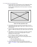
Figure 5.1 Check traverse level
7.
Release the traverse servo-drive by entering:
diagnostics/service/traverse/halt
8.
Align and measure as in steps
3.
and
4.
above.
9.
If the difference between the measurements is greater than
0.5
mm,
then an Engine level adjustment is required:
Adjust the feet to minimise creep and obtain an improved level. A
small adjustment of
1
/
4
to
1
/
2
turn (0.25 to 0.5 mm) on the engine feet
is usually sufficient.
10.
Repeat steps
2
.
to
9
.
until creep is within the specification.
11.
While the carriage moves along the traverse, observe the readhead
LED from the user end and ensure that it remains
green
(and does
not flash) for the
full
traverse. Ignore the
red
limit lights at the service
end.
CARRIAGE
RAIL
BALL CAGE
ALIGN AND
MEASURE
RUN TRAV. TEST
MEASURE AND CORRECT
FOR CAGE CREEP
3
1
2
V-GROOVE
Содержание alinte4page
Страница 1: ......
Страница 12: ...PRELIMINARIES...
Страница 29: ...ALINTE4PAGE INSTALLATION GUIDE 2 7 Figure 2 5 Autofeeder elevator warning label...
Страница 30: ...2 8 SAFETY ON THE ALINTE4PAGE Figure 2 6 Autofeeder elevator moving parts warning labels USER SIDE SERVICE SIDE...
Страница 34: ...2 12 SAFETY ON THE ALINTE4PAGE Figure 2 10 Interlock defeated warning labels typical alinte4page entry level...
Страница 35: ...ALINTE4PAGE INSTALLATION GUIDE 2 13 Figure 2 11 Interlock defeated warning labels typical alinte4page manual...
Страница 40: ...2 18 SAFETY ON THE ALINTE4PAGE Figure 2 13 Location of interlock covers alinte4page SAL 2 1...
Страница 48: ...2 26 SAFETY ON THE ALINTE4PAGE...
Страница 56: ...3 8 UNPACKING AND HANDLING...
Страница 98: ...4 42 INSTALLING ALINTE4PAGE EQUIPMENT AND SOFTWARE Figure 4 32 Removing transit fixing view 2...


