4-14
I
NSTALLING
ALINTE
4
PAGE
E
QUIPMENT
AND
S
OFTWARE
6.
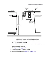
Adjust the engine height until the underside of the steel rule is
approximately
2 mm
above the lower input roller. Check from each
end.
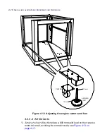
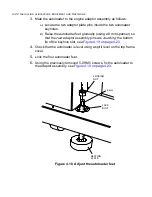
If the floor is outside the recommended minimum specification, set
the anchor feet to their lowest setting and re-adjust the processor.
Adjust the appropriate corners upwards to obtain improved levelling
using 12 mm and 16 mm spanners. See
Figure 4.12 on page 4-16
.
See
“Level the Engine” on page 4-15
for more information on levelling
the engine.
7.
Check the drum assembly is still level in both planes and re-adjust if
necessary.
NOTE: Do not use the engine panels for levelling.
8.
Refit the processor covers.
9.
Connect the comms cable from the processor to the engine.
10.
Connect the processor power cables.
Содержание alinte4page
Страница 1: ......
Страница 12: ...PRELIMINARIES...
Страница 29: ...ALINTE4PAGE INSTALLATION GUIDE 2 7 Figure 2 5 Autofeeder elevator warning label...
Страница 30: ...2 8 SAFETY ON THE ALINTE4PAGE Figure 2 6 Autofeeder elevator moving parts warning labels USER SIDE SERVICE SIDE...
Страница 34: ...2 12 SAFETY ON THE ALINTE4PAGE Figure 2 10 Interlock defeated warning labels typical alinte4page entry level...
Страница 35: ...ALINTE4PAGE INSTALLATION GUIDE 2 13 Figure 2 11 Interlock defeated warning labels typical alinte4page manual...
Страница 40: ...2 18 SAFETY ON THE ALINTE4PAGE Figure 2 13 Location of interlock covers alinte4page SAL 2 1...
Страница 48: ...2 26 SAFETY ON THE ALINTE4PAGE...
Страница 56: ...3 8 UNPACKING AND HANDLING...
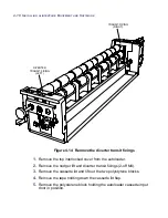
Страница 98: ...4 42 INSTALLING ALINTE4PAGE EQUIPMENT AND SOFTWARE Figure 4 32 Removing transit fixing view 2...


