ALINTE
4
PAGE
I
NSTALLATION
G
UIDE
4-25
4.
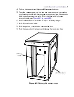
Pull out the cassette and tighten all four castor locknuts.
5.
Push the cassette back into the bay and make sure that the locating
pins locate smoothly into the cassette, and you can hear the cassette
latch ‘snap’ to engage correctly. Check that the latch is hooked
around the pin, see
Figure 4.21 on page 4-26
.
6.
If the cassette fails to latch then re-adjust the trolley height.
7.
Refit the autoloader doors.
8.
Refit the protect cover and the service side door.
9.
Refit the cassette lid, bumpers and release the input door flap.
Figure 4.20 Remove the protect cover
PROTECT
COVER
ADAPTOR ASSEMBLY
Содержание alinte4page
Страница 1: ......
Страница 12: ...PRELIMINARIES...
Страница 29: ...ALINTE4PAGE INSTALLATION GUIDE 2 7 Figure 2 5 Autofeeder elevator warning label...
Страница 30: ...2 8 SAFETY ON THE ALINTE4PAGE Figure 2 6 Autofeeder elevator moving parts warning labels USER SIDE SERVICE SIDE...
Страница 34: ...2 12 SAFETY ON THE ALINTE4PAGE Figure 2 10 Interlock defeated warning labels typical alinte4page entry level...
Страница 35: ...ALINTE4PAGE INSTALLATION GUIDE 2 13 Figure 2 11 Interlock defeated warning labels typical alinte4page manual...
Страница 40: ...2 18 SAFETY ON THE ALINTE4PAGE Figure 2 13 Location of interlock covers alinte4page SAL 2 1...
Страница 48: ...2 26 SAFETY ON THE ALINTE4PAGE...
Страница 56: ...3 8 UNPACKING AND HANDLING...
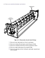
Страница 98: ...4 42 INSTALLING ALINTE4PAGE EQUIPMENT AND SOFTWARE Figure 4 32 Removing transit fixing view 2...


