Identification
Manual
ID ISC.MR102
FEIG ELECTRONIC GmbH
Page 113 of 153
H01113-4e-ID-B.docx
there is no response the Reader sends a EOF after EOF-PULSE-
DELAY and tries to sample the response after CMD-RES_DELAY
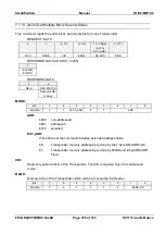
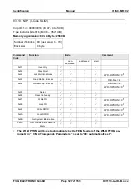
b100 = inventory request
The Reader tries to sample the response after CMD-RES-DELAY. If
ISO15693 “Nb_slot_flag” Flag is:
“0”
the Reader sends a EOF after EOF-PULSE-DELAY and tries
again to sample the response in the next timeslot ( after CMD-
RES_DELAY). This is done 16 times.
In this case the RSP-LENGTH defines the response length in
one timeslot. Transponder responses with other response
length will be ignored. If there is a CRC error in one of the
timeslots the protocol status is set to 0x02 [CRC error]. The us-
er should calculate which Transponder data hold the CRC error.
“1”
the Reader sends back the received data.
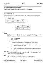
b101= request with grid position of response
The Reader tries to sample the response after ISO15693-3 CMD-RES-
DELAY. If there is no response the Reader sample at the time/grid spec-
ified in MULTIPLE 302us GRIDS. If there is no response the command
sends back status "no Transponder" 0x01. The maximum value for
MULTIPLE 302us GRIDS is 125 (
302,08us * 125 = 37,76ms)
Depending on the Error-Flag in the Transponder response the length of
the sample data is:
- 4 Byte if Error-Flag is "1"
- REP-LENGTH if Error-Flag is "0"
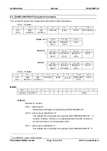
b110= read request without any ISO15693 specific data checks and ISO15693
data interpretation
Response is sampled corresponding to CMD-RES-DELAY.
cause by the fact that no data check is performed inside of the Reader
all data with response length same as response length specified in the
Host command to the Reader will be transfers with status 0x00. If re-
sponse length of data from Transponder and response length specified
in the Host command to the Reader are unequal, status 0x01 “No Tran-
sponder” will be the response of the Reader.
The user of the command mode 6 has to control the data coding and
decoding option of the Reader by setting CFG8/Byte 4
– ISO-Mode in
the manner the Reader should code the data in the RF forward link and
decode the data in the RF return link.
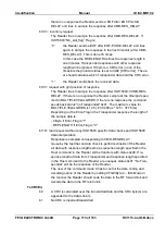
TxCRCEn:
b0
A CRC is calculated over the transmitted data and the CRC byte(s) are
appended to the data stream
b1
No CRC is inserted/transmitted

