background image

Identification 

Manual 

ID ISC.MR102 


FEIG ELECTRONIC GmbH 

Page 92 of 153 

H01113-4e-ID-B.docx 


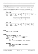
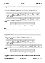
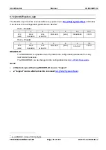
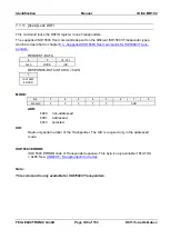
7.1.5. [0x24] Write Multiple Blocks 

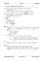
This command writes one or more data blocks. 

REQUEST-DATA 

1 Byte 

UID_LNG 

Bytes 

1Byte 


0x24 

MODE 

UID_LNG 

UID 

BANK 


1 Byte 

A_PW_LGT 

Bytes 

1 or 2 Bytes 

( def. by 

EXT_ADR) 

1 Byte 

1 Byte 

DB-N times 

DB-SIZE 

Bytes 


A_PW_LGT 

A_PW 

DB-ADR 

DB-N 

DB-SIZE 

DB 


Repeated DB-

N times 

RESPONSE-DATA (STATUS = 0x03) 

(8) 

DB-ADR-E 

(DB-ADR-E)

1


RESPONSE-DATA (STATUS = 0x95) 

(9) 

TAG ERROR 

DB-ADR-E 

(DB-ADR-E)

1


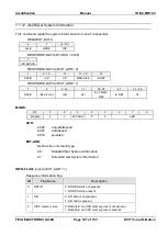
MODE:


Bit: 

Function  

EXT_ADR 

UID_LF 


ADR 

ADR: 

b000 

non-addressed 

b001 

addressed 

b010 

selected 


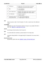
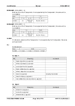
UID_LF: 

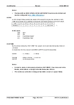
If this bit is set the parameter UID_LNG must inserted into the protocol. 

b0: 

The protocol UID_LNG doesn't include the UID_LNG byte and  
the UID field has a fixed length of 8 byte, from byte 6 to byte 13. 

b1: 

The protocol includes the parameter UID_LNG. The UID has a variable 
length as defined in UID_LNG. 


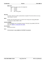
1

 used in extended address mode 

Содержание ID ISC.MR102

Страница 1: ...MANUAL final public B 2018 07 24 H01113 4e ID B docx ID ISC MR102 Standard Reader from Firmware Version 2 10 or higher...

Страница 2: ...for your useful tips The instructions given in this manual are based on advantageous boundary conditions FEIG ELECTRONIC GmbH does not give any guarantee promise for perfect function in cross environm...

Страница 3: ...h these bit spaces are reserved for future extensions or for internal testing and manufacturing functions These bit spaces must not be changed as this may cause faulty operation of the reader The foll...

Страница 4: ...Commands 12 2 3 Scan Mode 15 3 Interface 17 3 1 Protocol Frames of TCP IP protocol 17 3 2 Serial Data Format and Protocol Frames 18 3 3 CRC16 Calculation Algorithm 20 4 Configuration Parameters CFG 21...

Страница 5: ...R102 PoE SPAD102 E 62 4 24 CFG63 Customer Parameter 64 5 Protocols for Reader Configuration 65 5 1 0x80 Read Configuration 65 5 2 0x81 Write Configuration 66 5 3 0x83 Set Default Configuration Reset 6...

Страница 6: ...x2B Get System Information 101 7 1 13 0x2C Get Multiple Block Security Status 105 8 0xB3 Host commands for EPC Transponders 107 8 1 ISO18000 3M3 Commands 0xB3 108 8 1 1 0xB3 0x18 Kill 108 8 1 2 0xB3 0...

Страница 7: ...138 9 1 1 DATA Structure in Notification Mode 139 9 2 0x31 Read Data Buffer Info 139 9 3 0x32 Clear Data Buffer 140 9 4 0x33 Initialize Buffer 140 ANNEX 141 ANNEX A Codes of Transponder Types 141 ANNE...

Страница 8: ...d for the device The manufacturer shall not be held legally responsible for inaccuracies errors or omissions in the manual or automatically set parameters for a device or for an incorrect application...

Страница 9: ...e Bank added in CFG11 2e 15 04 15 57 CFG33 34 TCP IP Hostname implemented 60 CFG41 Additional parameter for LAN settings 127 NXP SLIX 2 integrated 3e 05 09 17 40 139 CFG11 Notification Mode with MAC o...

Страница 10: ...FO First in First out frq Frequency FSK Frequency Shift Keying h Hour Hz Hertz ID Identification IN Input LEN Length LOC Location LSB Least Significant Byte min Minutes ms Milliseconds MSB Most Signif...

Страница 11: ...nfiguration and control commands ISO Host Commands Scan Mode HID Notification Mode 2 1 Configuration Commands and Control Commands This method of data transmission is used for Reader configuration and...

Страница 12: ...g data in addressed mode the UID of the Transponder has to be known This is executed by sending the protocol 7 1 1 0x01 Inventory If a Transponder is located within the detection range of the Reader a...

Страница 13: ...only one Transponder is located within the range of the Reader The following chart will show the necessary steps for the communication with a Tran sponder in non addressed mode Host Terminal PC Reader...

Страница 14: ...include its UID The following chart will show the necessary steps for the communication with a Tran sponder in selected mode Host Terminal PC Reader Inventory to get the UID Transponder in antenna fi...

Страница 15: ...nsmitted user data is too large only the maxi mal number of transmitted data will be sent plus the end character Scan Mode via asynchronous interface The data will be sent out depending on their confi...

Страница 16: ...ey Code Different USB Key Code tables can be loaded into the reader using the demo program ISOStart USB Key codes for German and English are available Other languages can be created by the user and wi...

Страница 17: ...ribed below 3 1 Protocol Frames of TCP IP protocol If the Reader use the Ethernet Interface the data is packaged in a TCP IP protocol frame This means the whole data format and protocol frame which is...

Страница 18: ...he reply contains the transmitted control byte There is no reply from the Reader if there is a protocol frame failure Protocol frame Advanced Protocol Length Reader Host 1 2 3 4 5 6 n 2 STX 0x02 MSB A...

Страница 19: ...e STATUS 1 Includes the status message or protocol data from or to the Reader DATA Is a optional data field with variable length The number of DATA byte depend on the command The data will be sent alw...

Страница 20: ...s 8 Stop bits 1 Parity even default odd none 3 3 CRC16 Calculation Algorithm Polynom x16 x12 x5 1 CRC_POLYNOM 0x8408 Start Value 0xFFFF CRC_PRESET 0xFFFF C Example unsigned int crc CRC_PRESET for i 0...

Страница 21: ...C specifies the location of the configuration block RAM EEPROM MODE specifies one or all configuration blocks Bit 7 6 5 4 3 2 1 0 Function LOC MODE CFGn address of configuration block The EEPROM confi...

Страница 22: ...ective after writing saving this configuration block to RAM marked with 00 these bits or bytes are reserved for future extensions or for internal testing and manufacturing functions These bits or byte...

Страница 23: ...10 11 12 13 Contents 0x00 CFG_ACCESS 0x00 0x00 Default 0x00 0x00 0x00 0x00 READER ID AccessProtection Password Defines the password with which the host logs into the Reader for a read write access to...

Страница 24: ...he CFG0 regis ter if all configuration blocks are used The command 6 14 0xA0 Reader Login is used to enable configuration data access It is possible to disable the READER ID with an activation code if...

Страница 25: ...for applications with the RS485 interface Notes Do not configure address 255 Via the COM Adr 255 in the send protocol the Reader is able to be addressed at any time It answers then with the configured...

Страница 26: ...tive after writing saving configu ration block CFG1 to EEPROM and reset of the Reader Always 8 Data Bits and 1 Stop Bits should be used TR RESPONSE TIME AirInterface TimeLimit By means of this paramet...

Страница 27: ...enabled 0x00 support of Advanced Protocol Mode default 0x01 support of Advanced and Standard Protocol Mode We recommend to use Advanced Protocol Mode See 3 2 Serial Data Format and Protocol Frames SCA...

Страница 28: ...IG Network Reader with UDP commands UDP User Data Protocol READER MODE OperatingMode Mode By means of this byte the Reader mode can be defined Bit 7 6 5 4 3 2 1 0 Function NF E 0 0 0 0 0 SCAN E SCAN E...

Страница 29: ...used as an operation indicator Byte 0 1 2 3 4 5 6 Contents 0x00 0x00 0x00 IDLE STATE IDLE FLASH 0x00 0x00 Default 0xA9 0x00 Byte 7 8 9 10 11 12 13 Contents ACTIV STATE ACTIV FLASH ACTIV GRN TIME ACTIV...

Страница 30: ...DigitalIO Signaler Enable_StartupSignal When this option is selected the Reader will switch the LEDs on for two seconds to indicate that the Reader is ready after the Reader is supplied with power If...

Страница 31: ...een ActivationTime DigitalIO Signaler LED Red ActivationTime If a Transponder was detected the transmitter and the duration can be set by the bytes ACTIV STATE and ACTIV FLASH Each signal transmitter...

Страница 32: ...Transponder type is active A Transponder Driver HF ICode1 Driver for I Code 1 D Transponder Driver HF ISO_15693 Driver for ISO15693 J Transponder Driver HF ISO_18000 3M3 Driver for ISO18000 3M3 In pri...

Страница 33: ...erface Antenna HF Miscellaneous Enable_DCPower defines whether the Reader provides DC voltage on the antenna output for an external LED e g for ID ISC ANTS370 270 A See also Mounting Instruction b0 di...

Страница 34: ...0x01 0x0B 0x00 0x00 Byte 7 8 9 10 11 12 13 Contents ISO CMD OPTION 0x00 0x00 0x00 0x00 0x00 ISO Blocksize Default 0x03 0x04 ICODE MODE only I Code 1 Transponders Bit 7 6 5 4 3 2 1 0 Function 0 0 0 0 0...

Страница 35: ...Identifier to select a Transponder b0 Disabled b1 Enabled ISO 15693 OPTION Bit 7 6 5 4 3 2 1 0 Function 0 0 0 0 WR OPTION 0 0 WR OPTION Transponder HF ISO_15693 Miscellaneous WriteOption b00 automati...

Страница 36: ...e MFR table see 8 3 Supported ISO15693 Host commands for ISO15693 Transponders or if the transponder is used in the non addressed mode Range 0x01 0x1F A value of 0x00 will be automatically set to a bl...

Страница 37: ...1 b010 b001 b000 16 8 4 1 Each I Code 1 Transponder responds in a chosen timeslot Choosing too much timeslots compared to the number of Transponders in the antenna field means that only a small number...

Страница 38: ...on KSW 0x00 NXP Default 0x00 0x00 0x00 0x00 0x00 0x00 Byte 7 8 9 10 11 12 13 Contents ST 0x00 TI 0x00 0x00 0x00 0x00 Default 0x00 0x00 0x00 0x00 0x00 0x00 0x00 Note There are application notes availab...

Страница 39: ...e 39 of 153 H01113 4e ID B docx 4 8 CFG7 10 Reserved The configuration block CFG7 10 are reserved for future use Byte 0 1 2 3 4 5 6 Contents 0x00 0x00 0x00 0x00 0x00 0x00 0x00 Default Byte 7 8 9 10 11...

Страница 40: ...the data types for read operation Bit 7 6 5 4 3 2 1 0 Function Exten sion 0 TIMER 0 Byte Order DB 0 DB SNR SNR OperatingMode NotificationMode DataSelector UID OperatingMode ScanMode DataSelector UID b...

Страница 41: ...data types for read operation Bit 7 6 5 4 3 2 1 0 Function READ_CO MPLETE_ BANK COM Prefix COM Prefix Scan Mode only OperatingMode ScanMode DataFormat BusAddressPrefix b0 no COM Prefix is send b1 The...

Страница 42: ...B N 6 OperatingMode NotificationMode DataSource NoOfDataBlocks OperatingMode ScanMode DataSource NoOfDataBlocks Number of data blocks D START OperatingMode ScanMode DataSource FirstByte This parameter...

Страница 43: ...n Manual ID ISC MR102 FEIG ELECTRONIC GmbH Page 43 of 153 H01113 4e ID B docx Example data block Byte 0 1 2 3 4 5 6 7 Data 0x01 0x23 0x45 0x67 0x89 0xAB 0xCD 0xEF Output Data 0x23 0x45 0x67 0x89 D STA...

Страница 44: ...only for Scan Mode and Notification Mode TR ID sets the parameters for Transponder identification If several Transponders has the same content in the addressed data block only one da taset will be ge...

Страница 45: ...0 0 0 DB FORMAT DB FORMAT OperatingMode ScanMode DataFormat Format b0000 unformatted hex data In this case the data are transferred as they were read by the reader b0010 ASCII formatted hex data In t...

Страница 46: ...0D TAB 0x09 0x3B 0x2C 0x20 USER user defined in SEP USR none 0x00 Note Only one option could be selected SEP USR OperatingMode ScanMode DataFormat UserSeparationChar User defined separation character...

Страница 47: ...5 4 3 2 1 0 Function HEADER LEN END LEN END LEN OperatingMode ScanMode DataFormat NoOfUserEndChars b0000 END USR1 b0001 END USR1 b0010 END USR1 2 b0011 END USR1 2 3 HEADER LEN OperatingMode ScanMode D...

Страница 48: ...48 of 153 H01113 4e ID B docx 4 12 CFG14 15 Reserved The configuration block CFG14 15 is reserved for future use Byte 0 1 2 3 4 5 6 Contents 0x00 0x00 0x00 0x00 0x00 0x00 0x00 Default Byte 7 8 9 10 1...

Страница 49: ...ms Byte 7 8 9 10 11 12 13 Contents 0x00 0x00 0x00 0x00 0x00 0x00 0x00 Default 0x00 0x00 0x00 0x00 0x00 0x00 0x00 PER RESET TIME Transponder PersistenceReset Antenna No1 PersistenceResetTime The timer...

Страница 50: ...50 of 153 H01113 4e ID B docx 4 14 CFG17 19 Reserved The configuration blocks CFG17 19 are reserved for future use Byte 0 1 2 3 4 5 6 Contents 0x00 0x00 0x00 0x00 0x00 0x00 0x00 Default Byte 7 8 9 10...

Страница 51: ...3 2 1 0 Function 0 0 0 0 0 0 Weak Collision ISO18000 3M3 Weak Collision ISO15693 Weak Collision ISO15693 AirInterface Miscellaneous HF ISO_15693_ICode1 ErrorHandling Weak Collision b1 a weak collision...

Страница 52: ...ge 52 of 153 H01113 4e ID B docx 4 16 CFG21 Reserved The configuration blocks CFG21 are reserved for future use Byte 0 1 2 3 4 5 6 Contents 0x00 0x00 0x00 0x00 0x00 0x00 0x00 Default Byte 7 8 9 10 11...

Страница 53: ...0x00 0x00 0x00 CFG 23 Byte 0 1 2 3 4 5 6 Contents S_MASK Default 0x00 0x00 0x00 0x00 0x00 0x00 0x00 Byte 7 8 9 10 11 12 13 Contents S_MASK Default 0x00 0x00 0x00 0x00 0x00 0x00 0x00 S_MASK_LGT Transpo...

Страница 54: ...No1 Mask contains the bit string that the Tag compares against the memory location 18000 3M3 Adr Bit 0 15 16 31 32 47 48 63 64 79 80 3M3 Data CRC16 PC EPC S_MASK Example 18000 3M3 Adr Bit 0 15 16 31 3...

Страница 55: ...Identification Manual ID ISC MR102 FEIG ELECTRONIC GmbH Page 55 of 153 H01113 4e ID B docx 18000 3M3 Memory specification...

Страница 56: ...56 of 153 H01113 4e ID B docx 4 18 CFG24 32 Reserved The configuration blocks CFG24 32 are reserved for future use Byte 0 1 2 3 4 5 6 Contents 0x00 0x00 0x00 0x00 0x00 0x00 0x00 Default Byte 7 8 9 10...

Страница 57: ...11 12 13 Contents LAN HOSTNAME Default 0x00000000000000 CFG 34 Byte 14 15 16 17 18 19 20 Contents LAN HOSTNAME Default 0x00000000000000 Byte 21 22 23 24 25 26 27 Contents LAN HOSTNAME Default 0x00000...

Страница 58: ...58 of 153 H01113 4e ID B docx 4 20 CFG35 39 Reserved The configuration blocks CFG35 39 are reserved for future use Byte 0 1 2 3 4 5 6 Contents 0x00 0x00 0x00 0x00 0x00 0x00 0x00 Default Byte 7 8 9 10...

Страница 59: ...1 0x00 0x00 0x00 0x00 10001 IP_ADDRESS_LAN HostInterface LAN IPv4 IPAddress Defines the IP address for wired LAN connection Changing of this parameter only be comes effective after writing saving this...

Страница 60: ...IPv4 SubnetMask Defines the subnet mask for wired TCP IP connection Changing of this parameter only be comes effective after writing saving this configuration block to EEPROM and a 0x64 Sys tem Reset...

Страница 61: ...S_LAN HostInterface LAN IPv4 GatewayAddress Defines the gateway address for TCP IP connection Changing of this parameter only be comes effective after writing saving this configuration block to EEPROM...

Страница 62: ...gs for the notification channel Bit 7 6 5 4 3 2 1 0 Function ACK 0 0 0 0 0 DATA TRIGGER DATA TRIGGER b00 continuously The data records are notified always immediately For detailed message conditions s...

Страница 63: ...cationMode Transmission KeepAlive IntervalTime Defines the cycle time for keep alive notification max time period KEEP ALIVE TIME 0 65535 1s DEST IP ADDRESS OperatingMode NotificationMode Transmission...

Страница 64: ...of 153 H01113 4e ID B docx 4 24 CFG63 Customer Parameter The configuration block CFG63 is used for customer parameter Byte 0 1 2 3 4 5 6 Contents 0x00 0x00 0x00 0x00 0x00 0x00 0x00 Default Byte 7 8 9...

Страница 65: ...the byte CFG ADR Host Reader 1 2 3 4 5 6 7 8 STX 0x02 MSB ALENGTH LSB ALENGTH COM ADR 0x80 CFG ADR CRC16 Host Reader 1 2 3 4 5 6 7 20 21 22 STX 0x02 MSB ALENGTH LSB ALENGTH COM ADR 0x80 STATUS 7 CFG...

Страница 66: ...STX 0x02 MSB ALENGTH LSB ALENGTH COM ADR 0x81 CFG ADR CFG REC CRC16 Host Reader 1 2 3 4 5 6 7 8 STX 0x02 MSB ALENGTH LSB ALENGTH COM ADR 0x81 STATUS 9 CRC16 CFG ADR 10 Bit 7 6 5 4 3 2 1 0 Function LO...

Страница 67: ...8 STX 0x02 MSB ALENGTH LSB ALENGTH COM ADR 0x83 STATUS CRC16 CFG ADR Bit 7 6 5 4 3 2 1 0 Function LOC MODE CFGn Address of Configuration Block CFGn memory address of the required configuration block...

Страница 68: ...aud rate and actual parity of the Reader A USB reader will send status 0x00 OK if reader can be detected 6 2 0x55 Start Flash Loader This protocol starts the Flash Loader inside the Reader Use the win...

Страница 69: ...d off after a CPU Reset The communication interface will not be reset 6 4 0x64 System Reset This protocol allows you to reset the RF Controller Host Reader 1 2 3 4 5 6 7 8 STX 0x02 MSB ALENGTH LSB ALE...

Страница 70: ...0x65 CRC16 Host Reader 1 2 3 4 5 6 7 8 9 STX 0x02 MSB ALENGTH LSB ALENGTH COM ADR 0x65 STATUS 13 SW REV D REV 10 11 12 13 14 15 HW TYPE SW TYPE TR TYPE CRC16 SW REV Version of the firmware D REV Revi...

Страница 71: ...eader Types TR TYPE Displays the Transponders supported by the software Bit 15 14 13 12 11 10 9 8 Function ISO180 00 3M3 Bit 7 6 5 4 3 2 1 0 Function ISO 15693 I Code1 Note Only ID ISC MR102 E can sup...

Страница 72: ...ucture with several information s Mode 0 0x00 Controller Firmware 1 2 3 4 5 6 7 8 9 STX 0x02 MSB ALENGTH LSB ALENGTH COM ADR 0x66 STATUS 14 SW REV D REV 10 11 12 13 14 15 16 17 18 19 HW TYPE SW TYPE T...

Страница 73: ...1 PROTOCOL LENGTH ERROR TX BUF TX BUF is the maximum transmit buffer size of the Reader The host has to take in to ac count that a response protocol of the Reader can have this length DEV_ID Individua...

Страница 74: ...s After a RF Reset the Reader is not able to receive a new Transponder before expiration of trf After a RF Reset a Transponder which is located within the field has to be re selected The response of t...

Страница 75: ...al Noise Levels from the Reader Host Reader 1 2 3 4 5 6 7 STX 0x02 MSB ALENGTH LSB ALENGTH COM ADR 0x6D CRC16 Host Reader 1 2 3 4 5 6 7 12 13 14 STX 0x02 MSB ALENGTH LSB ALENGTH COM ADR 0x6D STATUS 18...

Страница 76: ...STX 0x02 MSB ALENGTH LSB ALENGTH COM ADR 0x6E MODE CRC16 Host Reader 1 2 3 4 5 6 7 n 2 n 1 n STX 0x02 MSB ALENGTH LSB ALENGTH COM ADR 0x6E STATUS DATA CRC16 MODE Reader Diagnostic Modes 0x01 Listing o...

Страница 77: ...red green 8Hz False Power No HF Power Check antenna connection OFF ON Wrong antenna Impedance absolute impedance value Z 50 Z Check and tune antenna ON ON HF short circuit OFF NOISE Noise to high Chec...

Страница 78: ...e new times included in the command if they are 0 Host Reader 1 2 3 4 5 6 7 STX 0x02 MSB ALENGTH LSB ALENGTH COM ADR 0x72 Mode OUT N 8 9 10 11 n 1 n OUT NR OUT S OUT TIME CRC16 Repeated OUT N times Ho...

Страница 79: ...put Bit 7 6 5 4 3 2 1 0 Function 0 0 0 0 0 0 OUTx mode OUTx mode b00 OFF b01 ON b10 FLASHING SLOW b11 FLASHING FAST OUT TIME By the values defined by OUT TIME the outputs can be activated temporary li...

Страница 80: ...ALENGTH LSB ALENGTH COM ADR 0x85 STATUS CRC16 TIMER Byte 6 7 8 9 TIME h min ms 0 23 0 59 0 59999 Note The internal system timer is not a real time clock RTC and the accuracy cannot be guaranteed 6 13...

Страница 81: ...0x02 MSB ALENGTH LSB ALENGTH COM ADR 0xA0 READER ID CRC16 Host Reader 1 2 3 4 5 6 7 8 STX 0x02 MSB ALENGTH LSB ALENGTH COM ADR 0xA0 STATUS 19 CRC16 READER ID The READER ID is a password which protect...

Страница 82: ...ode 1 ISO18000 3m3 7 1 0xB0 Host commands for ISO15693 Mandatory and Optional Commands 7 1 1 0x01 Inventory 7 1 2 0x02 Stay Quiet 7 1 3 0x22 Lock Multiple Blocks 7 1 4 0x23 Read Multiple Blocks 7 1 5...

Страница 83: ...r Host Reader 1 2 3 4 5 6 n 2 n 1 n STX 0x02 MSB ALENGTH LSB ALENGTH COM ADR 0xB0 REQUEST DATA CRC16 Host Reader 1 2 3 4 5 6 7 n 2 n 1 n STX 0x02 MSB ALENGTH LSB ALENGTH COM ADR 0xB0 STATUS RESPONSE D...

Страница 84: ...he antenna and reentered the antenna field or if a 6 7 0x69 RF Reset command was send to the Reader or if the Persistence Reset Time has expired 4 6 CFG5 Anticollision is disabled REQUEST DATA 6 7 0x0...

Страница 85: ...D only ISO15693 Transponders Data Storage Family Identifier IDD LEN Identifier Data Length defines the length of the IDD in Byte IDD Identifier Data of the Transponder Notes This command supports all...

Страница 86: ...ID B docx 7 1 2 0x02 Stay Quiet This command sets one Transponder to Quiet State REQUEST DATA 6 7 8 15 0x02 MODE UID MODE Bit 7 6 5 4 3 2 1 0 Function 0 0 0 0 0 ADR ADR b001 addressed UID Read only UI...

Страница 87: ...nsponders REQUEST DATA 6 7 8 9 1 or 2 Bytes def by EXT_ADR 1 Byte 0x22 MODE UID BANK DB ADR DB N RESPONSE DATA STATUS 0x03 7 DB ADR E RESPONSE DATA STATUS 0x95 7 8 ISO15693 ERROR DB ADR E MODE Bit 7 6...

Страница 88: ...First block number to be locked Depending on EXT_ADR First block can be any value between 0 and 255 or 0 and 65535 DB N Number of data blocks to be locked from the Transponder starting at DB ADR The...

Страница 89: ...e UID_LNG Bytes 1Byte 0x23 MODE UID_LNG UID BANK 1 Byte A_PW_LGT Bytes 1 or 2 Bytes def by EXT_ADR 1 Byte A_PW_LGT A_PW DB ADR DB N RESPONSE DATA STATUS 0x95 7 TAG ERROR RESPONSE DATA 7 8 9 10 n DB N...

Страница 90: ...is bit is set the reader will automatically read out all blocks of the selected memory bank Only available in the extended address mode b0 Reader reads out the memory blocks according to the settings...
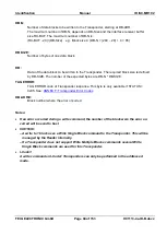
Страница 91: ...maximum number of DB N depends on DB Size and the interface transmit buffer size TX BUF The maximum number of DB N is TX BUF 10 DB Size 1 e g Block size 4 DB N 512 10 4 1 100 DB SIZE Number of bytes o...

Страница 92: ...d DB N times RESPONSE DATA STATUS 0x03 7 8 DB ADR E DB ADR E 1 RESPONSE DATA STATUS 0x95 7 8 9 TAG ERROR DB ADR E DB ADR E 1 MODE Bit 7 6 5 4 3 2 1 0 Function 0 0 EXT_ADR UID_LF ADR ADR b000 non addre...

Страница 93: ...ansponder which will be accessed by the Reader Bit 7 6 5 4 3 2 1 0 Function A_FLAG 0 0 0 0 0 BANK_NR BANK_NR In case of ISO18000 3M3 Transponder BANK_NR is defined as follows b00 reserved b01 EPC memo...

Страница 94: ...e number of the expected bytes are DB N DB SIZE TAG ERROR TAG ERROR code of Transponder response This byte is only available if STATUS 0x95 See ANNEX F Transponder Error Codes DB ADR E Block number wh...

Страница 95: ...Transponder will automatically be set to Ready State REQUEST DATA 6 7 8 15 0x25 MODE UID RESPONSE DATA STATUS 0x95 7 ISO15693 ERROR MODE Bit 7 6 5 4 3 2 1 0 Function 0 0 0 0 0 ADR ADR b001 addressed...

Страница 96: ...TUS 0x95 7 ISO15693 ERROR MODE Bit 7 6 5 4 3 2 1 0 Function 0 0 0 0 0 ADR ADR b000 non addressed b001 addressed b010 selected UID Read only serial number of the Transponder The UID is required only in...

Страница 97: ...onders REQUEST DATA 6 7 8 15 8 16 0x27 MODE UID AFI RESPONSE DATA STATUS 0x95 7 ISO15693 ERROR MODE Bit 7 6 5 4 3 2 1 0 Function 0 0 0 0 0 ADR ADR b000 non addressed b001 addressed b010 selected UID R...

Страница 98: ...st commands for ISO15693 Transponders REQUEST DATA 6 7 8 15 0x28 MODE UID RESPONSE DATA STATUS 0x95 7 ISO15693 ERROR MODE Bit 7 6 5 4 3 2 1 0 Function 0 0 0 0 0 ADR ADR b000 non addressed b001 address...

Страница 99: ...ponders REQUEST DATA 6 7 8 15 8 16 0x29 MODE UID DSFID RESPONSE DATA STATUS 0x95 7 ISO15693 ERROR MODE Bit 7 6 5 4 3 2 1 0 Function 0 0 0 0 0 ADR ADR b000 non addressed b001 addressed b010 selected UI...

Страница 100: ...Host commands for ISO15693 Trans ponders REQUEST DATA 6 7 8 15 0x2A MODE UID RESPONSE DATA STATUS 0x95 7 ISO15693 ERROR MODE Bit 7 6 5 4 3 2 1 0 Function 0 0 0 0 0 ADR ADR b000 non addressed b001 addr...

Страница 101: ...8 20 21 22 25 DSFID INFO FLAG UID AFI EXT MEM SIZE IC REF CL MODE Bit 7 6 5 4 3 2 1 0 Function 0 0 EXT ADR 0 0 ADR ADR b000 non addressed b001 addressed b010 selected EXT ADR Defines the command type...

Страница 102: ...nded Get System Info parameter Field 0 One byte length of Info flag field 1 Two byte length of Info flag field UID Read only serial number of the Transponder The UID is required only in the addressed...

Страница 103: ...ck size in Bytes Number of blocks IC REF IC reference version of the Transponder If not supported by the Transponder this value will return 0x00 CL Command List Byte 22 25 content CL Byte 4 CL Byte 3...

Страница 104: ...tiple block is supported 5 Extended Get Multiple Security Status is supported 6 RFU 0 shall be returned 7 RFU 0 shall be returned CL Byte 4 Bit Meaning Comment 0 Read Buffer is supported Means Respons...

Страница 105: ...N SEC STATUS Repeated DB N times MODE Bit 7 6 5 4 3 2 1 0 Function 0 0 EXT_ADR 0 0 ADR ADR b000 non addressed b001 addressed b010 selected EXT_ADR If this bit is set the command includes extended addr...

Страница 106: ...h security status is requested First block number can be any value between 0 and 255 DB N Number of Security data blocks to be read from the Transponder starting at DB ADR The maximum number of DB N i...

Страница 107: ...command sends special commands to EPC Transponder Host Reader 1 2 3 4 5 6 n 2 n 1 n 0x02 n COM ADR 0xB3 REQUEST DATA CRC16 Host Reader 1 2 3 4 5 6 7 n 2 n 1 n 0x02 n COM ADR 0xB3 STATUS RESPONSE DATA...

Страница 108: ...Byte K_PW_LNG K_PW RECOM Bits MODE Bit 7 6 5 4 3 2 1 0 Function 0 0 0 EPC_LF RECOM ADR ADR b000 non addressed b001 addressed EPC_LF If this bit is set the parameter EPC_LNG must inserted into the pro...

Страница 109: ...assword K PW Kill Password RECOM Bits Recommissioning Bits according to EPC Global description Bit 7 6 5 4 3 2 1 0 Function 0 0 0 0 0 Asserted 3SB 2SB LSB Notes ISO18000 3M3 A ISO18000 3M3 Transponder...

Страница 110: ...t the parameter EPC_LNG must inserted into the protocol b1 The protocol includes the parameter EPC_LNG The EPC has a variable length as defined in EPC_LNG EPC_LNG Is a optional parameter and depends o...

Страница 111: ...ONIC GmbH Page 111 of 153 H01113 4e ID B docx Notes ISO18000 3M3 A ISO18000 3M3 Transponder can be locked in non addressed mode only Lock data LOCK_DATA has to contain the kill code which is written t...

Страница 112: ...1 n CMD RSP DELAY MULTIPLE 302 GRIDS REQUEST DATA CRC16 Host Reader 1 2 3 4 5 6 7 n 2 n 1 n STX 0x02 MSB ALENGTH LSB ALENGTH COM ADR 0xBF STATUS 20 RESPONSE DATA CRC16 MODE Bit 7 6 5 4 3 2 1 0 Functi...

Страница 113: ...302us GRIDS If there is no response the command sends back status no Transponder 0x01 The maximum value for MULTIPLE 302us GRIDS is 125 302 08us 125 37 76ms Depending on the Error Flag in the Transpon...

Страница 114: ...delay for Transponder response ISO15693 t1 e g ISO15693 maximum value 0x846A 590ns 20ms REQUEST DATA Complete Transponder request without SOF CRC16 and EOF Note The read and write option FLAGS in the...

Страница 115: ...tion Mode Comment non addressed addressed select 0x01 Inventory 0x02 Stay Quiet 0x22 Lock Multiple Blocks 0x23 Read Multiple Blocks Security Status is always 0x00 0x24 Write Multiple Blocks 0x25 Selec...

Страница 116: ...cks Security Status is always 0x00 0x24 Write Multiple Blocks 0x25 Select 0x26 Reset to Ready 0x27 Write AFI 0x28 Lock AFI 0x29 Write DSFID 0x2A Lock DSFID 0x2B Get System Information 0x2C Get Multipl...

Страница 117: ...lect 0x26 Reset to Ready 0x27 Write AFI WR OPTION 0 or 1 0x28 Lock AFI WR OPTION 0 or 1 0x29 Write DSFID 0x2A Lock DSFID 0x2B Get System Information 0x2C Get Multiple Block Security Status The Custom...

Страница 118: ...e Comment non addressed addressed select 0x01 Inventory 0x02 Stay Quiet 0x22 Lock Multiple Blocks 0x23 Read Multiple Blocks Security Status is always 0x00 0x24 Write Multiple Blocks 0x25 Select 0x26 R...

Страница 119: ...lock size 4 byte WR OPTION 0 WR OPTION 0 Command Code Function Mode Comment non ad dressed addressed select 0x01 Inventory 0x02 Stay Quiet 0x22 Lock Multiple Blocks 0x23 Read Multiple Blocks 0x24 Writ...

Страница 120: ...ock Multiple Blocks 0x23 Read Multiple Blocks Single Read 0x24 Write Multiple Blocks 0x25 Select 0x26 Reset to Ready 0x27 Write AFI 0x28 Lock AFI 0x29 Write DSFID 0x2A Lock DSFID 0x2B Get System Infor...

Страница 121: ...tion Mode Comment non addressed addressed select 0x01 Inventory 0x02 Stay Quiet 0x22 Lock Multiple Blocks 0x23 Read Multiple Blocks 0x24 Write Multiple Blocks 0x25 Select 0x26 Reset to Ready 0x27 Writ...

Страница 122: ...addressed select 0x01 Inventory 0x02 Stay Quiet 0x22 Lock Multiple Blocks 0x23 Read Multiple Blocks Single Read 0x24 Write Multiple Blocks 0x25 Select 0x26 Reset to Ready 0x27 Write AFI 0x28 Lock AFI...

Страница 123: ...essed addressed select 0x01 Inventory 0x02 Stay Quiet 0x22 Lock Multiple Blocks 0x23 Read Multiple Blocks 0x24 Write Multiple Blocks 0x25 Select 0x26 Reset to Ready 0x27 Write AFI 0x28 Lock AFI 0x29 W...

Страница 124: ...Multiple Blocks WR OPTION 0 0x23 Read Multiple Blocks DB Size 4 0x24 Write Multiple Blocks DB Size 4 WR OPTION 0 0x25 Select 0x26 Reset to Ready 0x27 Write AFI WR OPTION 0 0x28 Lock AFI WR OPTION 0 0x...

Страница 125: ...Multiple Blocks WR OPTION 0 0x23 Read Multiple Blocks DB Size 4 0x24 Write Multiple Blocks DB Size 4 WR OPTION 0 0x25 Select 0x26 Reset to Ready 0x27 Write AFI WR OPTION 0 0x28 Lock AFI WR OPTION 0 0...

Страница 126: ...ultiple Blocks WR OPTION 0 0x23 Read Multiple Blocks DB Size 4 0x24 Write Multiple Blocks DB Size 4 WR OPTION 0 0x25 Select 0x26 Reset to Ready 0x27 Write AFI WR OPTION 0 0x28 Lock AFI WR OPTION 0 0x2...

Страница 127: ...ed addressed select 0x01 Inventory 0x02 Stay Quiet 0x22 Lock Multiple Blocks WR OPTION 0 0x23 Read Multiple Blocks DB Size 4 0x24 Write Multiple Blocks DB Size 4 WR OPTION 0 0x25 Select 0x26 Reset to...

Страница 128: ...bit ACCESS and 32 bit KILL password 64 bit EPC excluding 16 bit CRC 16 and 16 bit PC 240 bit TID including unique 48 bit serial number 96 bit User memory 512 bit Command Code Function Mode Comment no...

Страница 129: ...ntory 0x02 Stay Quiet 0x22 Lock Multiple Blocks 0x23 Read Multiple Blocks Single Read 0x24 Write Multiple Blocks 0x25 Select 0x26 Reset to Ready 0x27 Write AFI 0x28 Lock AFI 0x29 Write DSFID 0x2A Lock...

Страница 130: ...d addressed select 0x01 Inventory 0x02 Stay Quiet 0x22 Lock Multiple Blocks 0x23 Read Multiple Blocks LRIS2k Single Read 0x24 Write Multiple Blocks 0x25 Select 0x26 Reset to Ready 0x27 Write AFI 0x28...

Страница 131: ...02 Stay Quiet 0x22 Lock Multiple Blocks 0x23 Read Multiple Blocks 0x24 Write Multiple Blocks WR OPTION 0 0x25 Select 0x26 Reset to Ready 0x27 Write AFI WR OPTION 0 0x28 Lock AFI WR OPTION 0 0x29 Write...

Страница 132: ...E 00100101b 25h ST25DV04K JF 00100110b 26h ST25DV16K IE ST25DV64K IE 00100111b 27h ST25DV16K JF ST25DV64K JF memory organization for ST25DV64K 64 x 32 x 4 Byte 64kBit Number of blocks 2048 user area 0...

Страница 133: ...iple Blocks WR OPTION 0 0x25 Select 0x26 Reset to Ready 0x27 Write AFI WR OPTION 0 0x28 Lock AFI WR OPTION 0 0x29 Write DSFID WR OPTION 0 0x2A Lock DSFID WR OPTION 0 0x2B Get System Information 0x3B E...

Страница 134: ...locks 11 user area 0 7 Block size 4 byte WR OPTION 1 Pro Product ID 0h 100b Bit 43 41 of UID memory organization 12 x 4 Byte 48Byte 8 4 Byte 256 Bit user data Number of blocks 12 user area 0 7 Block s...

Страница 135: ...0xA2 Write 2 Blocks 0xA3 Lock 2 Blocks 0xA4 Kill only Tag it HFI Pro 0xA5 WriteBlockPwd only Tag it HFI Pro Note Reading of more than one block in non addressed mode is only possible if parameter Read...

Страница 136: ...yte WR OPTION 1 Command Code Function Mode Comment non ad dressed addressed select 0x01 Inventory 0x02 Stay Quiet 0x22 Lock Multiple Blocks 0x23 Read Multiple Blocks 0x24 Write Multiple Blocks 0x25 Se...

Страница 137: ...ing the non addressed mode the WR OPTION must be set manually to WR OPTION 1 Note The Write_2_Blocks command and Lock_2_Blocks command will be used automati cally by the reader This will only become a...

Страница 138: ...as fast as possible if the notification trigger is set to continuously or a very short cycle time in time triggered mode is defined To prevent a notification overflow in a host application the acknowl...

Страница 139: ...Blocks byte no 1 2 3 4 4 DB N DB SIZE DB N DB SIZE DB Timer byte no 1 4 TIMER MAC byte no 6 MAC ADR 9 2 0x31 Read Data Buffer Info The command Read Data Buffer Info reads the actual parameters of the...

Страница 140: ...Reader 1 2 3 4 5 6 7 STX 0x02 MSB ALENGTH LSB ALENGTH COM ADR 0x32 CRC16 Host Reader 1 2 3 4 5 6 7 8 STX 0x02 MSB ALENGTH LSB ALENGTH COM ADR 0x32 STATUS 22 CRC16 9 4 0x33 Initialize Buffer The comman...

Страница 141: ...Inventory command ANNEX C Time Behavior of the Asynchronous Interface The execution times of the asynchronous interface depend on The extent of the data that needs to be read or written Type and amou...

Страница 142: ...and ISO15693 Transponders All times apply to the following parameters ISO15693 MODE 4 5 CFG4 Transponder Parame ters AFI disabled Anticollision enabled only ISO15693 Transponder driver active The modu...

Страница 143: ...Identification Manual ID ISC MR102 FEIG ELECTRONIC GmbH Page 143 of 153 H01113 4e ID B docx...

Страница 144: ...not able to read the Transponder anymore 0x02 Data False CRC16 data error at received data 0x03 Write Error Negative plausibility check of the written data Attempt to write on a read only storing area...

Страница 145: ...ed for future use 0x16 Write Protect The configuration block is reserved for future use 0x17 Firmware activation required The firmware must be activated first using ISOStart demo program and the comma...

Страница 146: ...x6E Reader Diagnostic The antenna configuration isn t correct Check the antenna cables and the antenna matching The environment is too noisy The RF power doesn t have the configured value 0x92 No vali...

Страница 147: ...nnot be changed 0x13 The specified block was not successfully programmed 0x14 The specified block was not successfully locked 0xA0 0xDF Custom command error codes all others reserved for future use Er...

Страница 148: ...LR1002 50 ID ISC MU02 54 ID ISC MRU102 55 ID ISC MRU200 56 ID ISC MRU200 U 60 ID ISC PRH101 61 ID ISC PRH101 U USB Version 62 ID ISC PRHD102 63 ID ISC PRH102 71 ID ISC PRH100 U USB Version 72 ID ISC P...

Страница 149: ...149 of 153 H01113 4e ID B docx ANNEX H Examples for Read Data The setting LSB first and MSB first gives the direction of the received data bytes ISO15693 Host Command DB Size of the Transponder 4 byt...

Страница 150: ...G_ACCESS AccessProtection Lock_CFG14 Expert 0 9 1 6 1 CFG_ACCESS AccessProtection Lock_CFG15 Expert 0 9 1 7 1 CFG_ACCESS AccessProtection Lock_CFG16 Expert 0 10 1 0 1 CFG_ACCESS AccessProtection Lock_...

Страница 151: ...4 5 1 ISO 15693 OPTION WR OPTION Transponder HF ISO_15693 Miscellaneous WriteOption 4 6 1 2 2 TID Length Transponder Miscellaneous TIDLength Expert 4 11 1 IDDIB Transponder Miscellaneous IdentifierIn...

Страница 152: ...nMode Filter TransponderValidTime 12 0 2 TR_ID TR ID SOURCE OperatingMode Miscellaneous TransponderIdentification Source Expert 12 2 1 TR_ID TR ID DB ADR OperatingMode Miscellaneous TransponderIdentif...

Страница 153: ...AUTONEGOTIATION HostInterface LAN Autonegotiation Disable 41 4 1 3 1 ENABLE HOSTNAME HostInterface LAN Hostname Enable 41 4 1 4 1 DUPLEX HostInterface LAN Autonegotiation Duplex 41 4 1 5 1 SPEED HostI...

Отзывы: