


the motor or bearing pedestal shaft
must be replaced. Surface corrosion
must be removed so that seals can
slide freely during assembly. The shaft
diameter should be no smaller than
.002" below the nominal fractional seal
sizes. Remove any nicks or burrs which
may have occurred during disassembly.
Re-clean parts as necessary.
5D Reassembly
All parts should be visually inspected
and cleaned or replaced as outlined in
5C above.
1. The seal seat (#125) must be
installed in the motor bracket (#1)
before the bracket is installed on the
OQVQT6QKPUVCNNVJGUGCV
a. Place the motor bracket face up
QPCƀCVUWTHCEG
b. Apply a coating of compatible
lubricant to the elastomer portion
of the seat to aid with installation.
c. Carefully press the seat, smooth
side up, into the seat cavity of the
motor bracket. Thumb pressure
KUWUWCNN[UWHſEKGPVVQKPUVCNNVJG
seat.
2. Install the motor bracket. This is best
done with the motor standing on end.
Make sure that both the "C"-face of
the motor and the feet of the motor
bracket are clean. Slide the motor
bracket over the shaft onto the motor.
3. Install the rotating element (#12).
Lubricate I.D. of the rotating element.
Place the rotating element on the
shaft with the carbon end towards the
seat. Place the spring over the shaft,
with the backing plate up and com-
press the spring to locate the rotating
element against the seat. If this fails
to seat the rotating element gently
push the rotating element down with
a thin blade screwdriver being careful
not to damage the seat or the rotating
element.
4. Compress and hold the seal spring
slightly below the snap ring groove
and install the snap ring (#4). Make
sure the snap ring is locked in the
groove.
5. Install the impeller key (#23) into the
shaft keyway.
6JGKORGNNGTKUCUNKRſVCPFUJQWNF
UNKFGQPſTON[DWVGCUKN[WPVKNKVUVQRU
against the impeller wearing surface.
Force should not be required or used
to install the impeller in the correct
position. The impeller hub should
be facing out away from the motor
bracket. Refer to Figure 5-2.
7. Next, rotate the impeller by hand, the
impeller should move freely.
2NCEGVJGNCTIGő1ŒTKPIKPVQVJG
QWVUKFGő1ŒTKPIITQQXGKPVJGOQVQT
bracket. Place the two (2) smaller "O"
rings (#8) into the smaller "O" ring
grooves.
9. Place the cover (#2) over the motor
bracket and install the four (4) M6-1
X 80mm bolts (#19). Tighten the bolts
systematically, alternating diagonally
across the cover. DO NOT exceed
7-11 ft. lbs. of torque or damage to
the motor "C"-face may occur.
5E Testing and Final Adjustment
The pump is now ready for installation.
Final adjustments will be made with the
pump in operation.
%QPPGEVCNNRKRKPICPFſNNVJGRWOR
YKVJƀWKF
2. Reconnect the electrical connections,
referring to the colored or numbered
tape used to mark the wires.
3. Make sure all valves are opened, and
ƀWKFYKNNƀQYVJTQWIJVJGU[UVGO
5VCTVVJGRWORCPFOCMGVJGſPCN
adjustments to the M6 bolts holding
the cover on. These nuts and bolts
must be torqued to about 7-11 ft.
lbs. to obtain proper performance.
5. Check for leaks on pump and piping.
Special attention should be given to
the seal area at the rear opening in
the motor bracket.
7PFGTRTGUUWTGVJGKORGNNGTYKNNſPF
KVUőJ[FTCWNKEŒDCNCPEG
7. Using an amprobe or similar device,
check for motor overload.
8. While the impeller is seating, it is
common to experience some vari-
ance in readings. After a run-in period
the readings should level off.
This completes the adjustment and
testing phase. The pump is ready for
service.
BEARING PEDESTALS
A. Preliminary
B. Disassembly
C. Inspection of Components
D. Reassembly
E. Testing and Final Adjustments
5A Preliminary P2
1. Disconnect the inlet and outlet piping
before unbolting the pump. If the
pipes are corroded, use penetrating
oil on the threads to aid in removal.
2. Unbolt the pump from the base and
remove. Disassembly instructions for
the pump are found in Section 5, T31
PUMP ENDS. All work on the unit
should be performed on an elevated
workbench whenever possible.
The disassembly and reassembly
procedures are broken into two sections
EQXGTKPIVJGHQNNQYKPIWPKVU
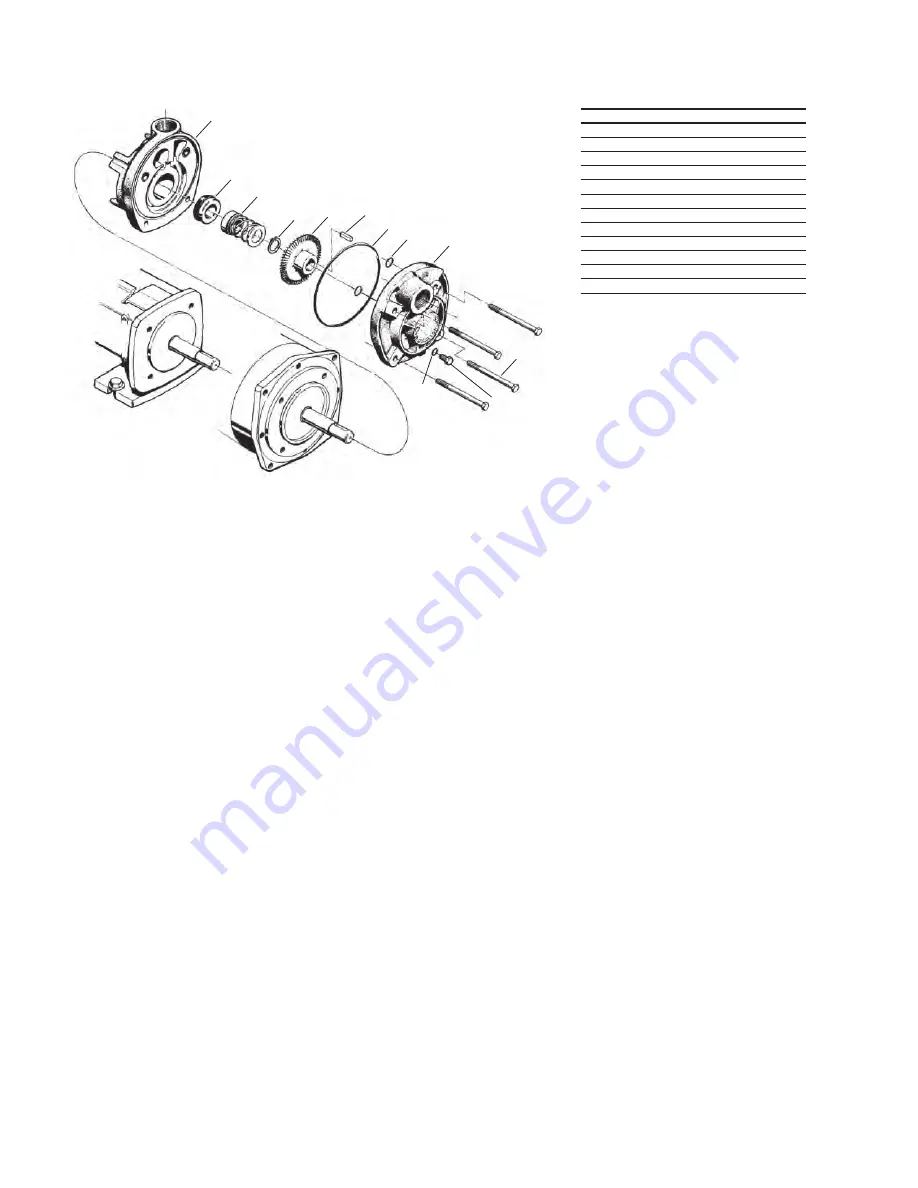
Figure 5-2
22
125
1
12
4
11
23
8
7
2
19
T31 CLOSE COUPLED PUMP
7A
NAME/DESCRIPTION PART NO. QTY.
Motor Bracket
1
1
Cover
2
1
"O" Ring/Casing
7
1
"O" Ring/Drain Plug
7A
1
"O" Ring/Thru Bolt
8
2
Snap Ring
4
1
Impeller
11
1
Seal Rotating Element
12
1
Seal Stationary Seat
125
1
Thru Bolt
19
4
Pipe Plug
22
1
Key/Impeller Drive
23
1
;
^
ͬEΖ
Ɛ
ĂĨƚĞƌ
&^ͲϬϮϯϲ
Ϳ
149
Содержание P2131
Страница 121: ... THIS PAGE INTENTIONALLY LEFT BLANK 115 ...
Страница 130: ...SECTION A APPENDIX 124 ...
Страница 131: ...A 1 Swagelok Fitting Installation Instructions 125 ...
Страница 135: ...A 2 PLC Data Sheet 129 ...
Страница 141: ...A 3 VERIFY Product Information 135 ...
Страница 147: ...A 4 WRS Pump Information 141 ...
Страница 158: ...A 5 Vacuum Leak Test Troubleshooting Guide 152 ...