Each VNC 325 codec has an integrated web interface. One codec in the VN-Matrix system
must be designated as the system controller, and the controller can be any unit in the
system, whether it is configured as an encoder or decoder. All normal system configuration
and control is via the web interface of the designated controller. Using a computer on the
same network and a standard web browser, such as Mozilla
®
Firefox
®
or Microsoft® Internet
Explorer®, you can configure any VNC 325 unit in the system.
Video signals that are connected to a VNC 325 codec that is configured as an encoder are
compressed into a data stream for transport across a local area or wide area network. At the
far end of the network, one or more VNC 325 codecs configured as decoders decode the
compressed stream back into the original video signal format.
The VNC 325 that is configured as an encoder accepts audio that is embedded in the input
video and that complies with the following SMPTE standards:
•
SMPTE 299M —
24-bit digital audio
•
SMPTE 272M-A —
20-bit digital audio
The embedded audio groups can be transported with the associated video content. Audio
can be sent as received (transparent mode) or as a single stereo pair (stereo mode). Stereo
mode results in a lower bit rate and reduces the network load. The VN-Matrix system also
supports simple compression of the stereo audio.
A dedicated RS-232 port is available for distributing RS-232 data with the coded/decoded
video, such as for control of projector.
A VN-Matrix 325 system is comprised of at least two devices, one configured as an encoder
and the other as a decoder. However, multiple encoders and decoders can co-exist on the
same network. On a given network, any decoder can display the source provided by any
encoder.
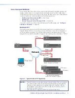
Figure 1
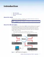
, on the preceding page, shows a basic VN-Matrix 325 system. In this
example, either of the two encoder streams can be routed to any or all three decoder units.
The configuration of each device, including the source that is displayed at each destination,
can be set using any PC or laptop on the same network, using the VN-Matrix 325 web
pages. In this example, the codec that is labeled IP Decoder 3 is the system controller.
Source (digital video) data from a VNC 325 encoder can be distributed to multiple decoders
and displays (one-to-many) or to a single decoder and display (point-to-point). Video data is
transported from the source (encoder) to the display (decoder) using one of three methods:
•
Multicast real time protocol (RTP) —
One source (encoder) and an infinite number of
displays (decoders)
•
Unicast RTP —
Single source (encoder) to single display (decoder), but it can also be
used for up to four displays
•
Unicast transport control protocol (TCP) —
Single source (encoder) to single display
(decoder). This method should be used
only
for single point-to-point transfer of data.
Each method, with its advantages and disadvantages and a sample connection diagram, is
described in “
Data Transport Methods
” in the “Installation“ section.
The units are housed in 1U high metal enclosures that can be mounted in any standard
19-inch rack or under furniture with optional mounting kits.
The external 100 VAC to 240 VAC, 50-60 Hz power supply provides worldwide power
compatibility.
VN-Matrix 325 Serial Digital Over IP CODEC • Introduction
2


