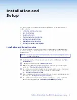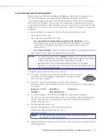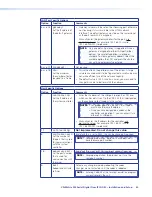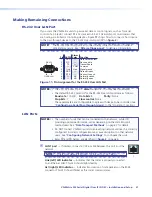
Low-level Network Configuration
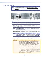
Before connecting a LAN port (see
item
d
or
item
e
on figure
2
and on page 6) on any
VNC 325 to the network, you need to establish the network settings of each unit.
You also need to select one codec in the VN-Matrix system as the controller and designate
that codec, by its IP address, in each codec. All normal system configuration and control is
via the network interface for the designated controller, which functions as the server for the
VN-Matrix. The controller can be any unit in the system, whether configured as an encoder
or decoder.
In a typical installation, you need to enter the following settings for each codec:
•
The IP address of the codec
•
The subnet mask (netmask) of the codec
•
For a network that is dedicated exclusively to the VN-Matrix
, which is
the preferred setup, Extron recommends that you use addresses in the range
of 192.168.0.1 through 192.168.0.254, with a subnet mask (netmask) of
255.255.255.0.
•
For an open network
, contact the system administrator for a range of IP addresses.
•
The IP address of the codec that is selected as the controller
NOTES:
• You need to manually assign a
known
IP address for the controller into each
codec in the VN-Matrix. This allows each VN-Matrix 325 device in the system
to be set to recognize the IP address of the device controller.
•
Because Dynamic Host Configuration Protocol (DHCP) can change IP
addresses, it is not practical to use this protocol. Extron recommends that you
use a static IP address scheme.
Change the network settings for all units as follows:
1.
Connect a null modem serial cable from the serial port of a computer
REMOTE
to the Remote port (see
item
a
on figure
2
and on page 6) on the
VNC 325 to be configured.
2.
On the PC, run a terminal emulation program such as the Extron
DataViewer utility or the HyperTerminal utility. The RS-232 protocol for the Remote port
is as follows:
Baud rate
: 115200
Data bits
: 8
Parity
: None
Stop bits
: 1
Flow control
: None
3.
Connect the power to the VNC 325 (see
item
c
on figure
2
and on page 6).
The VNC 325 sends setup and diagnostic data, which appears in the terminal emulator
window. After a few seconds the diagnostic data stops and the terminal emulator
displays a flashing cursor.
4.
Press the keyboard <Enter> key.
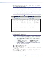
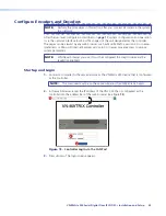
The VNC 325 responds with the following login prompt:
VN
Matrix(R)
Maintenance
Console:
ver
n
.
n
192.168.0.1
login:
NOTE:
The login prompt is preceded by the current IP Address of the unit,
192.168.0.1
in the example above.
5.
Type the default login
config
and press <Enter>. The connected unit responds with the
prompt
password:
.
VN-Matrix 325 Serial Digital Over IP CODEC • Installation and Setup
17

