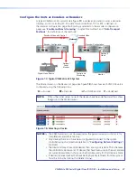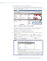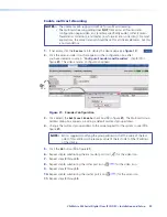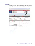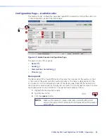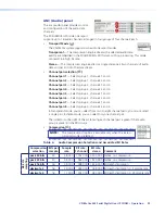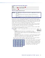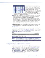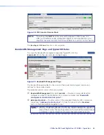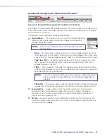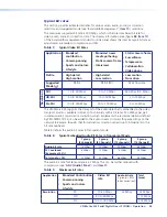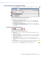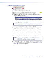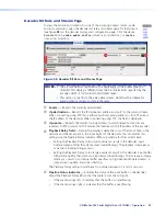
Device setup panel
The Device setup panel allows a codec to be
configured as either an encoder or a decoder.
(see “
Configure Encoders or Decoders
“). The
panel consists of the followings:
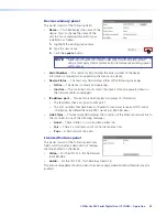
•
Device Type
— Select
create
source
,
create
display
, or (if the device is already configured)
change
device
type
.
•
Mode
:
•
Enable
— Normal operation; image transport is enabled.
•
Disable
— Image transport is disabled.
•
Test
— Select to suspend the active stream of the encoder and display a test
pattern on the SDI Out connector (
item
f
in figure
2
and on page 7). See “
Test
Pattern
“ in the “Reference Information” section for the test patterns.
•
Identify
— Select (check) this box to overlay the device name (see “
Device summary
panel
“) on the content that is output on the rear panel SDI Out BNC connector.
•
Source Identify (decoder only)
— Select (check) this box to overlay the name of the
device that it is decoding (see “
Device summary panel
“).
•
Data Interface
— The selection defines which of the two network interfaces,
LAN port 1 (
Cat6
) or LAN port 2 (
Fibre
) to use for data transport.
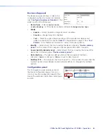
•
Multicast TTL
— This value sets the Time To Live (TTL — the number of routers that the
multicast packet crosses
between routed networks before it is dropped) for multicast
packets.
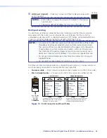
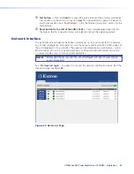
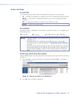
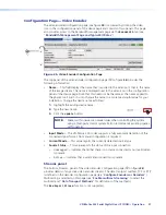
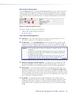
Configuration panel
— or —
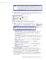
NOTE:
The icons displayed in this box are
available only after you create a
source or display.
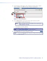
The Configuration panel provides access to
the device configuration pages. Click on an
icon to access the configuration page for that
device. The example at right shows selecting an
encoder.
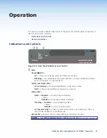
VN-Matrix 325 Serial Digital Over IP CODEC • Operation
36

