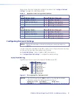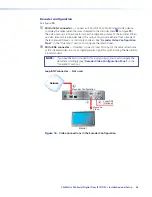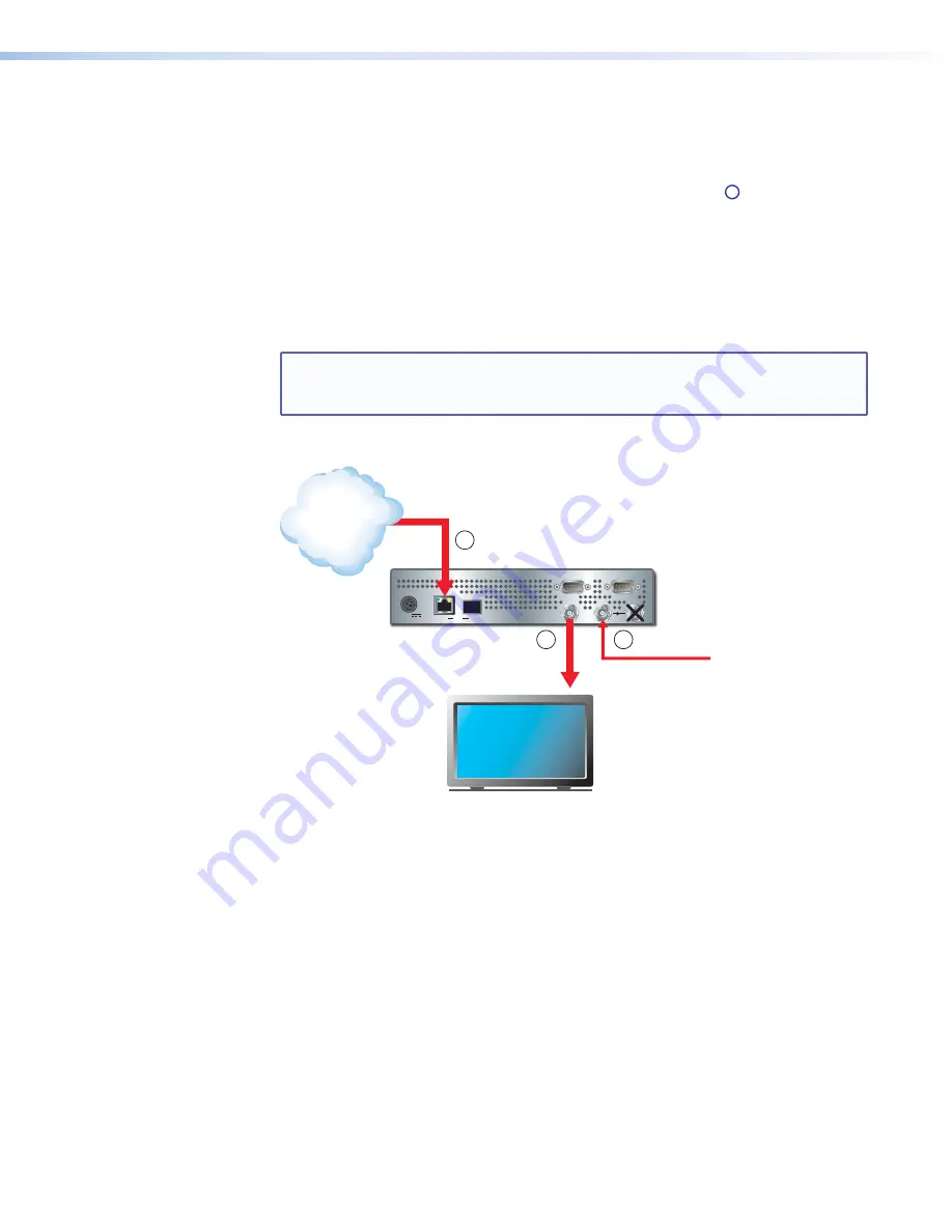
Decoder configuration
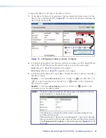
See figure
14
.
a
SDI Out BNC connector
— Connect an SDI, HD-SDI, or 3G-SDI digital video device
to display the digital video that was streamed to the decoder (item
B
on figure
14
).
The video output is in the same format as the originating source at the encoder. When
no video streams are being decoded, this output can provide either a frozen image of
the last received frame or a static splash screen. See “
Decoder Video Configuration
Panel
“ in the “Operation” section to configure the splash screen.
b
SDI In BNC connector
— If desired, connect a local SDI input of the same refresh rate
as the streamed video to act as a digital genlock signal for synchronizing the decoder to
a local standard.
NOTE:
If you use the SDI In connector for a synch signal, you must configure the
decoder accordingly (see “
Decoder Video Configuration Panel
“ in the
“Operation” section).
Loop BNC connector
—
Not used
.
12V DC
3A MAX
POWER
LAN
1
2
OPTICAL
REMOTE
SDI
OUT
SDI
IN
RS-232
OVER LAN
Decoder Configuration
Decoded
Video
Monitor
Local SDI
(Optional)
Network
B
1
2
Figure 14.
Video Connections in the Encoder Configuration
VN-Matrix 325 Serial Digital Over IP CODEC • Installation and Setup
24

