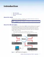
background image

Highly efficient compression algorithms

 — The VN-Matrix 325 system uses a minimal 

amount of data to transport video and audio across the network.

NOTE:


It is crucial to the effective operation of VN-Matrix 325 that sufficient data 

throughput be achieved, especially where multiple sources are encoded. 
The network efficiency is directly affected by the speed and configuration of 
each element, such as switchers and routers, within its infrastructure. The 

VN-Matrix 325 system achieves optimum transmission results over a dedicated 
1 Gbps network (1000Base-T, also known as Gigabit Ethernet).

Rack mounting

 — One or two 1U high, half-rack metal enclosure units can be mounted in 

any standard 19-inch rack with optional mounting kits.

Under furniture mounting

 — Using optional Extron surface mount kit

Power

 — The external 100 VAC to 240 VAC, 50-60 Hz power supply provides worldwide 

power compatibility.


VN-Matrix 325 Serial Digital Over IP CODEC • Introduction

4

Содержание VN-Matrix 325

Страница 1: ...User Guide VN Matrix 325 Streaming AV Products SDI HD SDI 3G SDI Over IP Codec 68 2122 01 Rev A 12 11 ...

Страница 2: ... verwenden sollten Sie alle Sicherheits und Bedienungsanleitungen genau durchlesen und verstehen Aufbewahren der Anleitungen Die Hinweise zur elektrischen Sicherheit des Produktes sollten Sie aufbewahren damit Sie im Bedarfsfall darauf zurückgreifen können Befolgen der Warnhinweise Befolgen Sie alle Warnhinweise und Anleitungen auf dem Gerät oder in der Benutzerdokumentation Keine Zusatzgeräte Ver...

Страница 3: ...n a commercial environment This equipment generates uses and can radiate radio frequency energy and if not installed and used in accordance with the instruction manual may cause harmful interference to radio communications Operation of this equipment in a residential area is likely to cause harmful interference in which case the user will be required to correct the interference at his own expense ...

Страница 4: ...mentioned in this guide the character 0 is used for the number zero and O represents the capital letter o Directory paths that do not have variables are written in the font shown here C Program Files Extron Variables are written in slanted form as shown here ping xxx xxx xxx xxx t SOH R Data STX Command ETB ETX Selectable items such as menu names menu options buttons tabs and field names are writt...

Страница 5: ...dio Encoder 38 Configuration Page Colfec and Rowfec Encoders 41 Bandwidth Management Page and Typical Bit Rates 42 Decoder Display and Configuration Page 47 Decoder Video Configuration Panel 47 Decoder Streams Configuration Panel 48 Decoder Bit Rate and Stream Page 49 Peripherals Page and Serial Port Control 51 Configuring a Serial Pass through Group 52 Firmware Upgrade Page 53 License Page 56 Acc...

Страница 6: ...VN Matrix 325 Serial Digital Over IP CODEC Contents vi ...

Страница 7: ...ations The VNC 325 codec can be configured to operate in one of two modes As an encoder to encode a source and stream it across a network As a decoder to decode a VN Matrix 325 encoded data stream from a network Network Netw VN MATRIX 325 SERIES SERIAL DIGITAL VIDEO OVER IP LAN 1 LAN 2 STATUS ALARM TEST VN MATRIX 325 SERIES SERIAL DIGITAL VIDEO OVER IP LAN 1 LAN 2 STATUS ALARM TEST k k k k k k k k...

Страница 8: ...t two devices one configured as an encoder and the other as a decoder However multiple encoders and decoders can co exist on the same network On a given network any decoder can display the source provided by any encoder Figure 1 on the preceding page shows a basic VN Matrix 325 system In this example either of the two encoder streams can be routed to any or all three decoder units The configuratio...

Страница 9: ... connected to an RS 232 serial port Final configuration and operation After the initial low level configuration all other configuration and operation of the VN Matrix 325 system is via either of two Ethernet ports of the system controller unit A computer that is running on the same network as either port can control the entire system using the built in HTML pages of that unit System control One co...

Страница 10: ...on of each element such as switchers and routers within its infrastructure The VN Matrix 325 system achieves optimum transmission results over a dedicated 1 Gbps network 1000Base T also known as Gigabit Ethernet Rack mounting One or two 1U high half rack metal enclosure units can be mounted in any standard 19 inch rack with optional mounting kits Under furniture mounting Using optional Extron surf...

Страница 11: ...stem in the order shown below Familiarize yourself with the signal and power connections on the codec see Rear Panel Features If desired mount the units see Mounting the Units Determine the data transport method and system routing that you will use in your system see Planning the System Architecture Use a computer connected to the Remote port on each unit to configure the network settings for that...

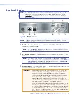
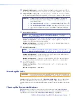
Страница 12: ...1 to wire the connector and Filter settings panel on page 60 to set critical alarms c Power Connector Connect the included 12 V power supply between this connector and a 100 VAC 240 VAC 50 60 Hz source CAUTIONS Always use power supplies specified by Extron for the codec Use of an unauthorized power supply voids all regulatory compliance certification and may cause damage to the supply and the unit...

Страница 13: ...ee Video Input Output and Loop Connections on page 23 for detailed connection diagrams Encoder configuration Connect an SDI HD SDI or 3G SDI digital video input for encoding and streaming to one or more decoders Decoder configuration If desired connect a a local SDI input or genlock signal of the same resolution and refresh rate to synchronize the decoder to a local standard h Loop BNC connector E...

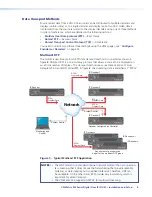
Страница 14: ...SERIES SERIAL DIGITAL VIDEO OVER IP LAN 1 LAN 2 STATUS ALARM TEST VN MATRIX 325 SERIES SERIAL DIGITAL VIDEO OVER IP LAN 1 LAN 2 STATUS ALARM TEST System Control VN MATRIX 325 SERIES SERIAL DIGITAL VIDEO OVER IP LAN 1 LAN 2 STATUS ALARM TEST VN MATRIX 325 SERIES SERIAL DIGITAL VIDEO OVER IP LAN 1 LAN 2 STATUS ALARM TEST VN MATRIX 325 SERIES SERIAL DIGITAL VIDEO OVER IP LAN 1 LAN 2 STATUS ALARM TEST...

Страница 15: ...1 through RTP4 System Control System Control Network VN MATRIX 325 SERIES SERIAL DIGITAL VIDEO OVER IP LAN 1 LAN 2 STATUS ALARM TEST k k k k k k k k k k rk rk rk rk rk ork VN MATRIX 325 SERIES SERIAL DIGITAL VIDEO OVER IP LAN 1 LAN 2 STATUS ALARM TEST VN MATRIX 325 SERIES SERIAL DIGITAL VIDEO OVER IP LAN 1 LAN 2 STATUS ALARM TEST VN MATRIX 325 SERIES SERIAL DIGITAL VIDEO OVER IP LAN 1 LAN 2 STATUS...

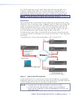
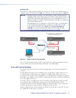
Страница 16: ...roller Monitoring and Control IP Encoder IP Decoder 1 IP Decoder 2 TCP IP Program Data TCP IP Program Data Each encoder is paired to a decoder with a point to point data link Figure 5 Typical Unicast TCP Application TCP is a connection based protocol Data is guaranteed to be delivered however excessive network traffic which impacts real time performance may delay delivery Data and Control Routing ...

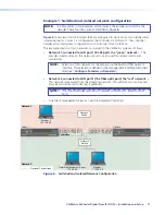
Страница 17: ...is defined in the management interface described later see Configure Encoders or Decoders Network 2 connected to LAN port 2 the fiber optic port the red network This network is separated from the streaming network This network also can be used for system control and monitoring if preferred NOTE The controller codec responds to inquiries on LAN port 2 as well as LAN port 1 A network management serv...

Страница 18: ...n Selections Codec 1 Option LAN Port 1 RJ 45 Option LAN Port 2 fiber optic 2 Address 172 28 0 1 12 Address 192 168 0 1 3 Netmask 255 255 0 0 13 Netmask 255 255 255 0 4 Gateway 172 28 0 254 14 7 Controller ip 172 28 0 1 Codec 2 Option LAN Port 1 RJ 45 Option LAN Port 2 fiber optic 2 Address 172 28 0 2 12 Address 192 168 0 2 3 Netmask 255 255 0 0 13 Netmask 255 255 255 0 4 Gateway 172 28 0 254 14 7 ...

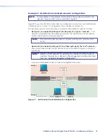
Страница 19: ...ber optic port the red network The encoder streams video on this network and it is also used for system control and monitoring NOTE Selection of this network for streaming is via the built in HTML network interface This selection is defined in the management interface described later see Configure Encoders or Decoders A network management server can also be integrated if required Network 1 Network...

Страница 20: ...elections Codec 1 Option LAN Port 1 RJ 45 Option LAN Port 2 fiber optic 2 Address 172 28 0 1 12 Address 192 168 0 1 3 Netmask 255 255 0 0 13 Netmask 255 255 255 0 4 14 Gateway 192 168 0 254 17 Controller ip 192 168 0 1 Codec 2 Option LAN Port 1 RJ 45 Option LAN Port 2 fiber optic 2 Address 172 28 0 2 12 Address 192 168 0 2 3 Netmask 255 255 0 0 13 Netmask 255 255 255 0 4 14 Gateway 192 168 0 254 1...

Страница 21: ...eway IP addresses the addresses on both sides of the router on the red network is set on LAN port 2 configuration option 14 for both codecs This architecture provides isolation between the video transport and simple network management protocol SNMP traffic NOTE The SNMP protocol includes a system of SNMP trap messages SNMP trap messages can be initiated by a network element and sent to the network...

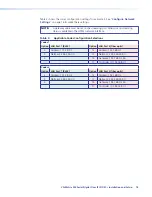
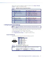
Страница 22: ...work Connect a computer to the Remote port a on each unit to configure the network settings for that unit Set one codec in the system as the controller See Serial Port Wiring below to make a cable for Remote port See Configure Network Settings to configure the network settings Serial Port Wiring Figure 9 shows how to connect a host device to the Remote port a RS 232 Function Pin 1 2 3 4 5 6 7 8 9 ...

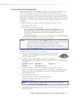
Страница 23: ...h VN Matrix 325 device in the system to be set to recognize the IP address of the device controller Because Dynamic Host Configuration Protocol DHCP can change IP addresses it is not practical to use this protocol Extron recommends that you use a static IP address scheme Change the network settings for all units as follows 1 Connect a null modem serial cable from the serial port of a computer REMO...

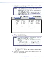
Страница 24: ... 16 mtu 1500 7 controller ip 192 168 0 101 17 ip forwarding 0 8 controller port 5432 18 webserver port 80 9 Exit Please select an option LAN Port 1 RJ 45 on figure 2 LAN port 2 Optical 4 5 Figure 10 Configuration Menu 7 Change the settings as needed as follows NOTES Do not include leading zeros when typing IP addresses For example type 192 168 0 104 do not type 192 168 000 104 Settings that you ne...

Страница 25: ... speed of the RJ 45 LAN port manually using the following subselections 1 auto_10_100_1000 2 auto_10_100 3 fixed_1000F 4 fixed_100F 5 fixed_100H 10 Speed Duplex LAN port 2 link speed Allows you to set the speed of the optical LAN port manually using the following subselections 6 fibre_auto_1000 7 fibre_fixed_1000F 1 and 11 Boot method Set static or dhcp Entering 1 11 toggles this option When DHCP ...

Страница 26: ...Set the IP address of the system controller Enter the IP address of the LAN port option 2 or 12 over which control data is sent to the VNC 325 that is designated as the controller into all codecs in the system NOTES For proper operation option 7 in all codecs must have the same IP address Once you have designated a codec as the controller using option 7 you can access it via either of its LAN port...

Страница 27: ...llows Baud rate 115200 Data bits 8 Parity None Stop bits 1 Flow control None These parameters are configurable to agree with device to be controller see Configuring a Serial Pass through Group in the Operation section LAN Ports NOTES The number of units that can be connected to the network while still providing optimal performance varies depending on the data transport method used See Data Transpo...

Страница 28: ...one cables do not support Gigabit Ethernet Do not stretch or bend cables Transmission errors can occur The Ethernet cable can be terminated as a straight through cable or a crossover cable and must be properly terminated for your application see figure 12 Crossover cable Direct connection between the computer and a VNC 325 encoder Patch straight cable Connection of a VNC 325 encoder to an Ethernet...

Страница 29: ... SDI In BNC connector Connect an SDI HD SDI or 3G SDI digital video input for encoding and streaming to one or more decoders via the LAN port item A on figure 13 c Loop BNC connector This connector provides a buffered loop through of the original source 12V DC 3A MAX POWER LAN 1 2 OPTICAL REMOTE SDI OUT SDI IN RS 232 OVER LAN Encoder Configuration Digital Video Source Optional Monitor Optional Mon...

Страница 30: ...nfigure the splash screen b SDI In BNC connector If desired connect a local SDI input of the same refresh rate as the streamed video to act as a digital genlock signal for synchronizing the decoder to a local standard NOTE If you use the SDI In connector for a synch signal you must configure the decoder accordingly see Decoder Video Configuration Panel in the Operation section Loop BNC connector N...

Страница 31: ...0 or newer provide access to various system parameters NOTE Whichever browser you use it must be configured to accept cookies and be JavaScript enabled Startup and Login 1 Connect a computer to the same network as the VN Matix 325 device that is configured as the controller NOTE The computer must be on the same subnet as the VN Matrix 325 units 2 In the web browser enter the IP address of the VNC ...

Страница 32: ... for the admin username and public for the public username The password can include letters numbers and the underscore character The password is case sensitive For the system configuration use the admin username 5 Click the LOG IN button or press Enter on the keyboard The VNC 325 HTML page opens to the Device List page see figure 16 The web page lists all VN Matrix devices that are connected to th...

Страница 33: ...ist page see figure 18 shows how each VNC 325 unit is configured using the following icons Encoder Decoder VNM Recorder Undefined NOTE If this is the initial setup none of the devices have been defined and thus show the icon in the Mode column 1 Figure 18 Selecting a Device NOTES The VNM Recorder is not documented in this guide Inclusion in this list is for completeness and reference only Only dev...

Страница 34: ...e 6 3 In the Device Setup panel b in figure 19 configure the device as either an encoder or decoder as follows Encoder Click the create source button A video icon an audio ANC icon and two forward error correction FEC icons appear in the Configuration box Proceed to step 6 Decoder Click the create display button A display icon appears in the Configuration box Proceed to step 4 NOTE If a device is ...

Страница 35: ...for multicast RTP streaming NOTE rtp m is available only if you have enabled multicast streaming See Enable multicast streaming Choose rtp for unicast RTP streaming Choose tcp for unicast TCP streaming NOTE See Data Transport Methods for more information 6 Click the Save All tab to save the configuration changes NOTE If you do not click Save All the configuration settings are lost when power is cy...

Страница 36: ...ion appears 2 4 3 1 Figure 21 Encoder Configuration 3 Click select the Multicast Enable check box b in figure 21 The Multicast Group Address dialog box appears providing a default multicast group address 4 Change the multicast group address to the value required for the system in use c in figure 21 NOTE Extron suggests modifying the group address so that the value of the last octet of this address...

Страница 37: ... underload condition exists Cycle power to clear the alarm LAN 1 and LAN 2 LEDs Lit or flashing The associated Ethernet connection is active Unlit The associated Ethernet connection is inactive Status LED Unlit Encoder No video input is detected or Decoder No network source is detected Flashing Encoder Unit is streaming video or Decoder Unit is receiving video Lit encoder only Video is present but...

Страница 38: ...s have been correctly set up for and connected to a network any further configuration and operation is via the network interface built in HTML pages of the unit designated as the controller The pages can be viewed by any web browser such as Mozilla Firefox version 4 0 or newer preferred or Microsoft Internet Explorer version 6 0 or newer provide access to various system parameters NOTE Whichever b...

Страница 39: ... this list is for reference only Only devices that are or have been configured to connect to the system controller using the procedure detailed in Configuring Network Settings are listed The device list may show more devices than are in your system This is because the controller maintains a list of devices that have been used in the past and are not currently available In this case the IP address ...

Страница 40: ... device on the device list page a Figure 25 shows the device page for a unit that is configured as an encoder 2 6 3 4 5 1 Figure 25 Typical Device Page for an Encoder The device page is divided into four information and configuration panels Device summary b Licensed features c Device setup d Configuration e VN Matrix 325 Serial Digital Over IP CODEC Operation 34 ...

Страница 41: ...down or the network cable is unplugged IP address port This read only field displays two pieces of information The IP address that is assigned to LAN port 1 The port numbers that have been configured for send and receive of UDP control information By default these are 9001 send and 5432 receive Link Status This read only field displays the condition of the Ethernet network link to the controller i...

Страница 42: ...panel on the content that is output on the rear panel SDI Out BNC connector Source Identify decoder only Select check this box to overlay the name of the device that it is decoding see Device summary panel Data Interface The selection defines which of the two network interfaces LAN port 1 Cat6 or LAN port 2 Fibre to use for data transport Multicast TTL This value sets the Time To Live TTL the numb...

Страница 43: ...name 3 Click the update button NOTE Spaces within names can cause issues when controlling the system using a third party control system Extron recommends avoiding spaces within names Input Mode The VN Matrix 325 codec supports a fully automatic detection of the connected signal format No manual configuration is required Current Mode This value reports the currently detected source type Source Stat...

Страница 44: ...ame of the audio and other audio data stream The name is displayed next to the anc audio icon in the configuration panel of the device page Note that this need not be the same as the name applied to the physical unit itself You can change the name to a more meaningful value for your installation Change the device name as follows 1 Highlight the existing device name 2 Type the new name 3 Click the ...

Страница 45: ... Selects group 3 channels 3 and 4 Channel pair 7 Selects group 4 channels 1 and 2 Channel pair 8 Selects group 4 channels 3 and 4 In Transparent mode you can select from two to eight channel pairs you cannot select a single pair In stereo mode you can select only one channel pair The indicator to the right of the list showing each channel pair is green if that audio group is present in the SDI sou...

Страница 46: ...e VN Matrix 325 products implement the recommendations defined by the PRo MPEG Code of Practice 3 CoP3 SMPTE 2022 standard Ñ FEC Mode The FEC can be applied as either column only or row and column Row FEC protects against the loss of a single packet It is the simplest method of protection and results in the lowest overhead in terms of bit rate and latency However it cannot handle consecutive packe...

Страница 47: ...op packets artificially in order to test the effectiveness of the FEC scheme Streams panel The audio encoder configuration page streams panel see figure 29 provides details of any active audio encoder streams The data transport method TCP or RTP is defined on the decoder configuration page see Configure Encoders or Decoders Audio multicasting is selected in this panel see Enable multicast streamin...

Страница 48: ...atial and temporal compression settings for the encoded source The available controls consist of two main panels a Bandwidth Management standard controls Provides a simple interface that configures a subset of the VN Matrix 325 compression toolset see Bandwidth management standard controls panel b Advanced controls Provides control of the complete VN Matrix 325 compression toolset see Advanced con...

Страница 49: ... a bit rate limit is applied Controlling the frame update rate whenever the bit rate limit is exceeded maintains the limit PBR F This is a peak bit rate mode The spatial quality is held constant until the bit rate limit is exceeded at which point additional spatial compression is applied to keep the bit rate at the specified limit NOTE If you cannot maintain the bit rate limit using only spatial c...

Страница 50: ...ovide visually lossless compression for HD content By default the offset between Luminance and Chrominance is set to 2 whenever the Advanced controls panel is hidden the Bandwidth Management controls panel Standard button is clicked û Temporal Compression mode check box Applies temporal compression to the bandwidth management causing data to be transferred only when a change occurs between frames ...

Страница 51: ...he frame rate is managed by setting a value for the Frame Drop Percentage see item û below Shared Flowrate This mode is the same as the Peak flow rate but the bit rate control is applied to the aggregate value for all streams from the encoder as would be the case if multiple maximum 4 Unicast RTP streams are chosen as the data transport method None See the Control mode drop down box in Bandwidth M...

Страница 52: ...upports the transport of the audio data that is embedded in the video transport Audio is available in blocks of 4 channels with a bit rate of 2 43Mbps per pair in stereo mode Forward error correction which implements the recommendations defined by PRO MPEG COP3 can be added to the audio stream to correct for packet drops on the network Be aware though that forward error correction can add up to 50...

Страница 53: ...tion Panel 1a 1c 1d 1b Figure 36 Decoder Video Configuration Panel Ä Name field This is the name that is displayed in the device list page This can be changed to any value Å Nodata splash checkbox Enables the display of a splash screen when the display device detects a break in the input data stream When this control is disabled the last decoded frame is displayed û Genlock checkbox Enables a a lo...

Страница 54: ...ransport of the audio content associated with the selected video stream the audio stream by selecting the Audio check box If enabled the selected audio stream is listed adjacent to the audio heading in the bandwidth list If Audio is not enabled the display is none û Fec checkbox Enable or disable the transport of the row rowfec and column colfec content associated with the selected video stream by...

Страница 55: ...dress to which reception statistics are reported In RTP unicast and TCP modes this field reports the IP address of the encoder d Playback Delay field Defines the playback delay the sum of the transit time in the network and the time spent in the input buffer of the decoder You can modify this setting Use the PIpeline Status indicator e as a guideline for the correct value Setting the Playback Dela...

Страница 56: ... data source NOTE The reported bit rate in figure 39 is for the video stream only See Typical bit rates on page 46 to estimate values for the Audio and error correction streams ã Packets sec row Displays the number of data packets per second received from the source Dropped packets row Displays the number of data packets dropped during the associated interval time Dropped packets are counted when ...

Страница 57: ...RIAL DIGITAL VIDEO OVER IP LAN 1 LAN 2 STATUS ALARM TEST VN MATRIX 325 SERIES SERIAL DIGITAL VIDEO OVER IP LAN 1 LAN 2 STATUS ALARM TEST VN MATRIX 325 SERIES SERIAL DIGITAL VIDEO OVER IP LAN 1 LAN 2 STATUS ALARM TEST VN MATRIX 325 SERIES SERIAL DIGITAL VIDEO OVER IP VN MATRIX 325 SERIES SERIAL DIGITAL VIDEO OVER IP LAN 1 LAN 2 STATUS ALARM TEST Server RS 232 Client Client Client Client TCP TCP TCP...

Страница 58: ...als page see a on figure 41 set the mode to either server or client If you select client the destination drop down box c appears 1 Configuring the Server Configuring a Client 1 4 4 2 2 2 2 2 2 2 2 2 2 3 Figure 41 Configuring a Serial Pass through Group 5 Configure the baud rate data bits stop bits parity and handshake settings as required b 6 In the destination drop down box select passthrough for...

Страница 59: ... the upgrade file from the control PC to a temporary storage area on the controller The controller VNC 325 only Prepare Unpack and copy the upgrade into all units All VNC 325s Activate Activate the upgrade in temporary mode It can be abandoned if problems occur All VNC 325s Commit Permanently commit to the upgrade All VNC 325s Upload Device Upgrade Status WAIT Prepare Activate WAIT Automatic Reboo...

Страница 60: ...mitting to the controller upgrade Uploading the upgrade to the controller codec Upload the file to a temporary storage area on the controller VNC 325 in accordance with the procedure below From this location it can be installed on all codecs in the system 1 Login to the network interface see Startup and Login in the Installation and Setup section 2 On the device list page click anywhere on the row...

Страница 61: ...he controller can hold a maximum of two upgrade files If another is loaded then the oldest file is deleted Installing the firmware prepare activate and commit stages Once the file is uploaded unpack and copy the new firmware from the controller into the VNC 325 alternate flash memory of each unit starting with the controller unit 1 Open the upgrade page see Uploading Copying the Upgrade to the Con...

Страница 62: ... READYTOCOMMIT 5 Test the system for correct operation 6 If everything is working correctly click the forward button The Device Upgrade Status field shows Committing and the percentage of progress This stage may last a few minutes When it is complete the Device Upgrade Status field shows WAIT and the Commited Version field displays the upgrade you just successfully commited NOTE If you experience ...

Страница 63: ...M Recorder is not documented in this guide Inclusion in this list is for completeness and reference only 1 2 3 Figure 47 Passwords Panel Change a password as follows 1 Enter the existing password in the Current Password field for the account that you want to change a on figure 47 2 Enter the new password in both the New Password and Confirm fields for the account that you want to change b NOTES Th...

Страница 64: ...e as follows 1 Entering the local time in the New Time field in the format yyyy mm dd hh mm ss see a figure 48 1 2 Figure 48 Clock Management Panel 2 Click the Change Time button b Controller Licensing Panel The fields on this panel are set when the unit is manufactured and users should not attempt modify them in any way CAUTION If you do modify these fields the unit may become unstable VN Matrix ...

Страница 65: ...ve on the system Alarm Logs page see figure 51 This page provides a historical log of when an alarm condition was raised and cleared Device list page see figure 16 A traffic light symbol in the Status column represents the status of a device In the top right hand corner of each network interface page The device status and system status is displayed In addition the red LED located on the front pane...

Страница 66: ...e below Alarm Severity Description Critical When triggered a critical alarm Illuminates the red LED on the front panel of the affected unit Closes the normally open contacts and opens the normally closed contacts of the relay accessed via the RS 232 Over LAN port Displays the red traffic light indicator for the device on the device list page Warning When triggered displays the yellow traffic light...

Страница 67: ... through connector Critical reporting Bad source syncs Source is present unrecognized due to bad sync measurement Critical reporting No SDI source lock Source is present unable to lock Critical reporting Unsupported SDI Mode Source is present mode is not supported Critical reporting Unsupported Mode Not applicable to VNC 325 N A Bad Source Not applicable to VNC 325 N A Analogue Phasing error Not a...

Страница 68: ...erflow The incoming data rate is high reduce the pipeline delay Warning reporting Decoder buffer underflow The incoming data rate is too low increase the pipeline delay Warning reporting Bad video PLL The decoder cannot synchronize to the video data Warning reporting No decoder ANC data The decoder is not receiving any embedded audio ancillary data Warning reporting Missing ANC at decoder The deco...

Страница 69: ...lear event is listed together When more that 200 events occur the oldest event is deleted from the log Alarm events that are listed can be sorted by Type Raise Time and Severity Position the mouse over the desired sorting heading and left click to change the list order The list is refreshed each time that you change the sorting criteria Click the Clear Logs button to erase all logged alarm data VN...

Страница 70: ... you may need to change include The SNMP password The SNMP community value SNMP trap destination values SNMP Password Value The SNMP password is the same as the administrator password By default this is set to admin You must to enter the administrator password on the accounts page before SNMP can be used This process must be carried out for each of the following circumstances When first using the ...

Страница 71: ...tings panel see figure 52 on the alarm logs page The community string must match that in use by the NMS if not then it may not be possible to manage the VNC 325 device SNMP Trap Destination Values The Create Trap Destination field in the SNMP filter settings panel see figure 52 on the alarm logs page is used to add and remove destination IP addresses for NMS servers Multiple destinations may be ad...

Страница 72: ...nput 2 for loop through 1 with messaging overlay option Nominal level 0 8 Vp p Impedance 75 ohms Data rates 1 5 Gbps to 3 0 Gbps Vertical frequency 23 97 Hz to 60 Hz depending on signal format Resolution range 525i 625i 720p 1080i 1080p 1080psf Video processing codec Compression PURE3 Codec Frame rate delay 35 ms 70 ms encoding decoding end to end Bit rate 6 Mbps to 250 Mbps Bit and frame rate con...

Страница 73: ...bit digital audio full sampling rate 16 bit digital audio half sampling rate 16 bit digital audio quarter sampling rate Sampling rates and bit depth 48 kHz 20 or 24 bit digital audio Standards SMPTE 299M SMPTE 272M A Transmitted payload 2 43 Mbps Control host ports codecs decoders Serial host control port 1 RS 232 male 9 pin D connector labeled Remote for VNC 325 configuration Baud rate and protoc...

Страница 74: ... F 40 to 70 C 10 to 90 noncondensing Operating 41 to 95 F 5 to 35 C 10 to 85 noncondensing Cooling Fan vents front to back Mounting Rack mount Yes Enclosure type Metal Enclosure 1 7 H x 8 75 W x 12 2 D 1U high half rack wide 4 3 cm H x 22 2 cm W x 30 9 cm D Height with feet is 2 1 5 3 cm Depth includes connectors Product weight 2 8 lbs 1 3 kg each Shipping weight 8 lbs 4 kg Regulatory compliance S...

Страница 75: ...03 MBU 149 Under desk mount kit 70 222 01 VNM 12 PSR 12 Unit Power Supply with Redundancy 70 762 01 VNM 12 PS 12 Unit Power Supply 70 763 01 Optional SFP Module LAN port 2 is an SFP mini GBIC Gigabit slot that accepts a copper or optical SFP compatible transceiver This part is not included with the codec and can be acquired locally Contact the Extron S3 Sales Technical Support Hotline if you have ...

Страница 76: ... an environment compatible with the maximum ambient temperature Tma 95 F 35 C specified by Extron Reduced air flow Installation of the equipment in a rack should be such that the amount of air flow required for safe operation of the equipment is not compromised Mechanical loading Mounting of the equipment in the rack should be such that a hazardous condition is not achieved due to uneven mechanica...

Страница 77: ...de display the test pattern on the SDI OUT connector Output format HD 1280 x 720 progressive SD 720 x 576 or 720 x 480 interlaced Figure 53 High Definition Test Pattern 1280 x 720 Figure 54 Standard Definition Test Pattern 720x480 720x576 VN Matrix 325 Serial Digital Over IP CODEC Reference Information 71 ...

Страница 78: ...mber This will begin the repair process USA 714 491 1500 Europe 31 33 453 4040 Asia 65 6383 4400 Japan 81 3 3511 7655 Units must be returned insured with shipping charges prepaid If not insured you assume the risk of loss or damage during shipment Returned units must include the serial number and a description of the problem as well as the name of the person to contact in case there are any questi...

Отзывы: