Commissioning
Field bus connection and configuration
16
Item No.: 099-008225-EWM01
4.4.2.4 Connection of the CANopen module
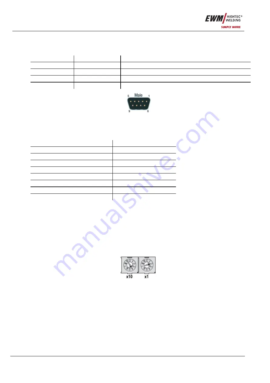
The field bus is connected via a 9-pole SUB-D plug connector (socket). The layout of the module signals
(plugs) is as follows:
Pin Signal
Function
2
CAN_L
Low signal cable of the CAN difference signal
3
CAN_GND
Reference mass of the CAN signal
5
CAN_SHLD
Connection for cable shield
7
CAN_H
High signal cable of the CAN difference signal
Figure 4-5
4.4.2.5 Setting the baud rate
The field bus module must be set to the baud rate used on the network using a selector switch:
Selector switch setting
Baud rate
1 10kbps
2 20kbps
3 50kbps
4 125kbps
5 250kbps
6 500kbps
7 800kbps
8 1Mbps
The baud rate setting is only active after switching on the supply voltage and after re-starting the
module.
4.4.2.6 Setting the subscriber address
The module must be assigned a unique address which is a one-off in the network before commissioning.
This is carried out via two selector switches in a range of 1 to 99. The right-hand switch selects the single
place digit, and the left-hand switch selects the tens place digit for the address setting. The setting is
carried out in decimal format:
Example: Address 42 = left-hand switch position 4 (x10) + right-hand switch position 2 (x1)
Figure 4-6
4.4.2.7 EDS configuration file
The module settings can be modified via an EDS file. In this case, however, the option of configuration via
the bus master is a requirement (not possible in all cases).
A suitable EDS files can be provided by EWM Hightec Welding GmbH if required.


