


Overview
Manual • Doc.-No.: C.3032.21 / Rev. 1.1
CAN-CBX_Pt100
Page 8 of 120
! "
#$%&
'()
% "*+
#,# -
%&
.
/&%-/+
0# $
+/ $/1-+/&& *+
023 453 6
7
8 9:; 9
8
< 8;
;=
>
?
; 9@ <
/A* +
BC DD&"
E5
FG
'H
; 8
<
9 :
I:
J
K
L
>
M
?
:
9 :
N
> K
O
PQ RS T
U VWX
NU
Y
9 :
N
VQ RSRU Z
[Q \V
']
'
'/1 ^
* +-
* +
# ,#-%&
.
/ &
% -
/ +
8=
<
N;;
O N
O
9 :
7
8 9:; 9
8
<8 ;
_`
a (]
a
'
/1 ^*+-
* +
']'a
'
/ 1^*+-* +
T b
>
<
:
<
; <:
<
1. Overview
1.1 Description of the Module
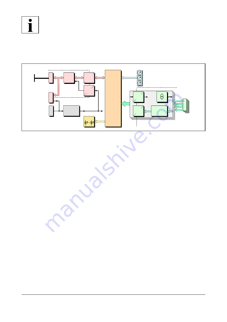
Fig. 1: Block circuit diagram of the CAN-CBX_Pt100 module
The CAN-CBX_Pt100 module is a CAN-CBX module designed for the connection of four temperature
sensors. Simple electric resistance measurement can also be performed.
Pt- and Ni- resistance sensors are supported. The sensor resistors can be connected in two- or four- wire
configuration.
The temperature sensors can be connected via four 5-pin Mini-Combicon connectors.
Linearisation according to NIST is achieved by the on board microcontroller.
The conversion of the four temperature sensor inputs is realized by four independent
cd
-converters.
The resolution achieved depends of the sample rate and the measuring current.
The CAN-CBX_Pt100 module is equipped with a MB90F497 microcontroller, that works with an
integrated SRAM. The firmware is held in the flash. The parameters are saved in a serial EEPROM.
The CAN interface is designed according to ISO11898-2 high-speed layer with electrical isolation and
supports bit rates up to 1 Mbit/s. The CANopen-node number and the CAN-bit rate can be easily set
via coding switches.
The CAN-CBX_Pt100 features the possibility to connect the power supply and the CAN bus signals
via the InRailBus connector (TBUS-connector) integrated in the mounting rail. Individual modules can
then be removed without interrupting the bus signals.
The module comes with CANopen® firmware according to CiA® 301 and supports the CiA DS 404
profile for measuring devices.