EPSON AcuLaser C4000/C4100/C3000
Revision F
Appendix
Wiring Diagrams and Signal Information
9-611
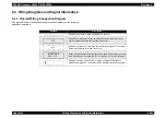
9.3.2 Wiring and Signal Descriptions between
Components
9.3.2.1 Configuration
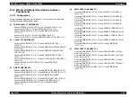
Wiring connection diagrams are divided into 11 sections and provide details
concerning connections between parts.
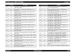
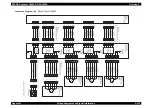
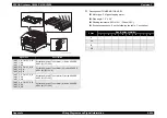
§1. POWER SUPPLY COMPONENTS
Connects PWBA MCU & HVPS (PL15.1.2) and LVPS (PL15.1.10).
Connects LVPS (PL15.1.10) and PWB DRIVE (PL15.1.15).
Connects PWB DRIVE (PL15.1.15) and PWBA MCU & HVPS
(PL15.1.2).
Connects LVPS (PL15.1.10) and FAN REAR (PL15.1.3).
Connects LVPS (PL15.1.10) and HARNESS ASSY AC SW (PL15.1.11).
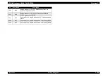
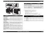
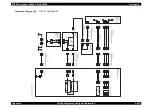
§2. CASSETTE COMPONENTS
Connects PWB DRIVE (PL15.1.15) and SWITCH SIZE TRAY 1
(PL4.2.8).
Connects PWB DRIVE (PL15.1.15) and SENSOR NO/LOW PAPER (N/
P) (PL4.3.4).
Connects PWB DRIVE (PL15.1.15) and SENSOR NO/LOW PAPER
(L/P) (PL4.3.4).
Connects PWB DRIVE (PL15.1.15) and SOLENOID FEED TRAY 1
(PL4.3.17).
Connects PWB DRIVE (PL15.1.15) and CLUTCH ASSY TURN TRAY 1
(PL4.3.18).
Connects PWBA MCU & HVPS (PL15.1.2) and PWB DRIVE
(PL15.1.15).
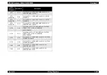
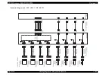
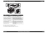
§3. DRIVE COMPONENTS
Connects PWB DRIVE (PL15.1.15) and DRIVE ASSY MAIN (PL14.1.2).
Connects PWB DRIVE (PL15.1.15) and DRIVE ASSY DEVE (PL14.1.1).
Connects PWB DRIVE (PL15.1.15) and DRIVE ASSY FUSER
(PL6.1.18).
Connects PWB DRIVE (PL15.1.15) and MOTOR ASSY DUP (PL8.1.8).
Connects PWB DRIVE (PL15.1.15) and FAN FUSER (PL1.1.9).
Connects PWBA MCU & HVPS (PL15.1.2) and PWB DRIVE
(PL15.1.15).
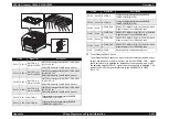
§4. DEVELOPER COMPONENTS 1
Connects PWB DRIVE (PL15.1.15) and SWITCH TCRU ASSY(Y)
(PL12.2.10).
Connects PWB DRIVE (PL15.1.15) and SWITCH TCRU ASSY(M)
(PL12.2.10).
Connects PWB DRIVE (PL15.1.15) and SWITCH TCRU ASSY(C)
(PL12.2.10).
Connects PWB DRIVE (PL15.1.15) and SWITCH TCRU ASSY(K)
(PL12.2.10).
Connects PWB DRIVE (PL15.1.15) and SENSOR TONER LOW (Y)
(PL12.2.9).
Connects PWB DRIVE (PL15.1.15) and SENSOR TONER LOW (M)
(PL12.2.9).
Connects PWB DRIVE (PL15.1.15) and SENSOR TONER LOW (C)
(PL12.2.9).
Connects PWB DRIVE (PL15.1.15) and SENSOR TONER LOW (K)
(PL12.2.9).
Connects PWBA MCU & HVPS (PL15.1.2) and PWB DRIVE
(PL15.1.15).
§5. DEVELOPER COMPONENTS 2
Connects PWB DRIVE (PL15.1.15) and HOLDER ASSY (Y) (Toner
Motor:Y) (PL12.2.5).
Connects PWB DRIVE (PL15.1.15) and HOLDER ASSY (M) (Toner
Motor:M) (PL12.2.6).
Connects PWB DRIVE (PL15.1.15) and HOLDER ASSY (C) (Toner
Motor:C) (PL12.2.7).
Connects PWB DRIVE (PL15.1.15) and HOLDER ASSY (K) (Toner
Motor:K) (PL12.2.8).
Connects PWBA MCU & HVPS (PL15.1.2) and PWB DRIVE
(PL15.1.15).
Содержание AcuLaser C3000 Series
Страница 1: ...EPSON AcuLaserC4000 AcuLaserC4100 AcuLaserC3000 Color Laser Page Printer SEPG01012 SERVICE MANUAL ...
Страница 20: ...C H A P T E R 1 PRODUCTDESCRIPTIONS ...
Страница 71: ...C H A P T E R 2 OPERATINGPRINCIPLES ...
Страница 118: ...C H A P T E R 3 TROUBLESHOOTING ...
Страница 318: ...C H A P T E R 4 DISASSEMBLYANDASSEMBLY ...
Страница 472: ...C H A P T E R 5 ADJUSTMENT ...
Страница 477: ...C H A P T E R 6 MAINTENANCE ...
Страница 491: ...C H A P T E R 7 AcuLaserC4100 ...
Страница 548: ......
Страница 549: ......
Страница 550: ......
Страница 551: ......
Страница 552: ......
Страница 553: ......
Страница 554: ......
Страница 555: ...C H A P T E R 8 AcuLaserC3000 ...
Страница 579: ...Model AcuLaser C3000 Board C569MAIN BOARD Sheet 1 of 5 Rev B ...
Страница 580: ...Model AcuLaser C3000 Board C569MAIN BOARD Sheet 2 of 5 Rev B ...
Страница 581: ...Model AcuLaser C3000 Board C569MAIN BOARD Sheet 3 of 5 Rev B ...
Страница 582: ...Model AcuLaser C3000 Board C569MAIN BOARD Sheet 4 of 5 Rev B ...
Страница 583: ...Model AcuLaser C3000 Board C569MAIN BOARD Sheet 5 of 5 Rev B ...
Страница 584: ...C H A P T E R 9 APPENDIX ...
Страница 617: ...EPSON AcuLaser C4000 C4100 C3000 Revision F Appendix Wiring Diagrams 9 602 Figure 9 6 P J Location 6 ...
Страница 644: ...EPSON AcuLaser C4000 C4100 C3000 Revision F Appendix Wiring Diagrams and Signal Information 9 629 ...
Страница 674: ......
Страница 675: ......
Страница 676: ......
Страница 677: ......
Страница 678: ......
Страница 679: ......
Страница 680: ......

