EPSON AcuLaser C4000/C4100/C3000
Revision F
Troubleshooting
Level 2 FIP
3-185
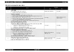
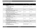
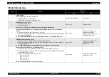
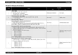
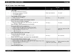
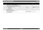
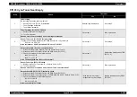
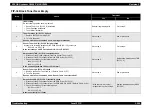
FIP-27 BTR Life Over
Step
Check
Treatment
Yes
No
1
Initial setting
Do the following checks show a problem?
• BTR Assy (PL9.1.2) installation
• Sensor TNR Full (PL6.1.13) installation
Reinstall applicable parts.
Go to step 2.
2
BTR Assy (PL9.1.2)
1. Remove the BTR Assy. (Refer to Ch4-4.2.12.2)
2. Look at the part of the BTR Assy that goes into the sensor element of the Sensor Toner
Full (PL6.1.13).
Is the part of the BTR Assy that goes into the sensor element of the Sensor Toner Full
blocked with recovered toner?
Replace the BTR Assy.
(Refer to Ch4-4.2.12.2)
Go to step 3.
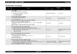
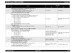
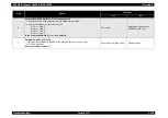
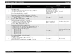
3
BTR Assy (PL9.1.2)
Are the transparent sections at the left and right of the BTR Assy part that goes into the
sensor element of the Sensor Toner Full (PL6.1.13) clean?
Is the BTR Assy part that goes into the sensor element of the Sensor Toner Full clean?
Go to step 4.
Clean the transparent surfaces.
4
BTR Assy (PL11.1.3)
1. Replace the BTR Assy. (Refer to Ch4-4.2.12.2)
2. Turn On the power.
Does an error occur even when a new BTR Assy is installed?
• With the tool: Go to step 5.
• Without the tool: Go to step 6.
End of procedure
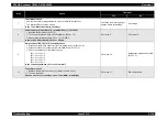
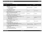
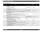
5
Sensor TNR Full (PL6.1.13) check
Use the Sensor TNR Full diagnosis tool to carry out a Digital Input Test.
Is the Sensor TNR Full functioning normally?
Go to step 9.
Go to step 6.
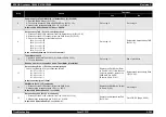
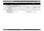
6
Sensor TNR Full (PL6.1.13) signal check
1. Remove the BTR Assy. (Refer to Ch4-4.2.12.2)
2. Insert an obstruction such as a piece of paper into the sensor element of the Sensor Toner
Full and then remove it.
3. Measure the following voltage at the relay connector between the Harness Assy TFLSNS
and the Harness Assy EEPROM (PL15.2.10).
P/J141-2 <=> P/J141-1
Is the voltage between P/J141-2 <=> P/J141-1 3.3V DC when the obstruction is inserted,
and 0V DC when it is removed?
Go to step 9.
Go to step 7.
Содержание AcuLaser C3000 Series
Страница 1: ...EPSON AcuLaserC4000 AcuLaserC4100 AcuLaserC3000 Color Laser Page Printer SEPG01012 SERVICE MANUAL ...
Страница 20: ...C H A P T E R 1 PRODUCTDESCRIPTIONS ...
Страница 71: ...C H A P T E R 2 OPERATINGPRINCIPLES ...
Страница 118: ...C H A P T E R 3 TROUBLESHOOTING ...
Страница 318: ...C H A P T E R 4 DISASSEMBLYANDASSEMBLY ...
Страница 472: ...C H A P T E R 5 ADJUSTMENT ...
Страница 477: ...C H A P T E R 6 MAINTENANCE ...
Страница 491: ...C H A P T E R 7 AcuLaserC4100 ...
Страница 548: ......
Страница 549: ......
Страница 550: ......
Страница 551: ......
Страница 552: ......
Страница 553: ......
Страница 554: ......
Страница 555: ...C H A P T E R 8 AcuLaserC3000 ...
Страница 579: ...Model AcuLaser C3000 Board C569MAIN BOARD Sheet 1 of 5 Rev B ...
Страница 580: ...Model AcuLaser C3000 Board C569MAIN BOARD Sheet 2 of 5 Rev B ...
Страница 581: ...Model AcuLaser C3000 Board C569MAIN BOARD Sheet 3 of 5 Rev B ...
Страница 582: ...Model AcuLaser C3000 Board C569MAIN BOARD Sheet 4 of 5 Rev B ...
Страница 583: ...Model AcuLaser C3000 Board C569MAIN BOARD Sheet 5 of 5 Rev B ...
Страница 584: ...C H A P T E R 9 APPENDIX ...
Страница 617: ...EPSON AcuLaser C4000 C4100 C3000 Revision F Appendix Wiring Diagrams 9 602 Figure 9 6 P J Location 6 ...
Страница 644: ...EPSON AcuLaser C4000 C4100 C3000 Revision F Appendix Wiring Diagrams and Signal Information 9 629 ...
Страница 674: ......
Страница 675: ......
Страница 676: ......
Страница 677: ......
Страница 678: ......
Страница 679: ......
Страница 680: ......

