


EPSON AcuLaser C4000/C4100/C3000
Revision F
Operating Principles
Control
2-86
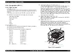
2.8.4.3 High Area Coverage Mode
When printing a series of pages with an image coverage area requiring toner
dispensing, the toner density inside the developer can become low.
To counter this, High Area Coverage Mode delays the feeding of the next sheet
of paper when the toner dispense time has reached its set value and continues
to allow toner dispensing.
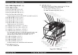
2.8.4.4 Admix Mode
There are times when High Area Coverage Mode will not be able to fully
counteract low density of toner inside the developer. In another case, by
bringing the printer to a location with low humidity after using it in an area of
high humidity, SENSOR ASSY ADC (PL6.1.11) measured values and toner
density standard values will differ greatly because the toner density standard
values will change with each environment.
To handle this, Admix Mode prevents a drop in toner density by activating toner
dispensing when the toner density control patch measurements taken by the
SENSOR ADC ASSY at the time of patch formation greatly falls below the
standard value.
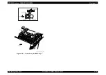
2.8.4.5 SENSOR ASSY ADC (PL6.1.11) LED Light Quantity
Control
The SENSOR ASSY ADC is a refection type density sensor that uses an
internal LED to shine light on a target, detect the reflected light with a receptor,
and send an electric signal corresponding to light quantities detected. In order
to correctly measure the density, it is necessary for the sensor output value
(reflected light quantity) from the BTR target (when no toner is present) to be
like a required value. The reflected light quantity will change according to the
condition of the BTR surface and the amount of dust on the SENSOR ASSY
ADC surface. For the reflected value to become a standard, the light emitted
from the LED must be controlled.
This control sets the light quantity as though the reflected light quantity were a
prescribed value and thereafter regulates quantities to be within the allowed
limits.
1) Light
Quantity
Setting
The reflected light quantity can change substantially when the BTR
ASSY (PL9.1.2) is replaced or the SENSOR ASSY ADC is cleaned.
This is assumed to happen, and setting is performed when power is
turned on or the front cover is closed. The LED light quantity is
increased gradually, and output from the SENSOR ASSY ADC
becomes the set value when it surpasses the prescribed value. At this
time, if the SENSOR ASSY ADC output cannot be set as the
prescribed value even at its maximum light quantity, then the sensor is
judged to be dirty. If the output is unusually high, the sensor is judged
to be damaged.
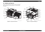
2) Light Quantity Adjustment
Light Quantity Adjustment is performed just before formation of the
toner density control patch when ADC is activated.
Light is emitted at the currently set LED light quantity, and SENSOR
ASSY ADC output is evaluated to see if it is within the fixed range. If
the output value is low, the fixed value for light quantity is increased the
next time ADC is activated. If the output value is high, the fixed value
for light quantity is reduced the next time ADC is activated.
At this time, if the value falls to the first minimum limit, the sensor is
judged to be dirty and an alarm is sounded. If the value falls to the
second minimum limit, the sensor is judged to be dirty and printing is
stopped.
Содержание AcuLaser C3000 Series
Страница 1: ...EPSON AcuLaserC4000 AcuLaserC4100 AcuLaserC3000 Color Laser Page Printer SEPG01012 SERVICE MANUAL ...
Страница 20: ...C H A P T E R 1 PRODUCTDESCRIPTIONS ...
Страница 71: ...C H A P T E R 2 OPERATINGPRINCIPLES ...
Страница 118: ...C H A P T E R 3 TROUBLESHOOTING ...
Страница 318: ...C H A P T E R 4 DISASSEMBLYANDASSEMBLY ...
Страница 472: ...C H A P T E R 5 ADJUSTMENT ...
Страница 477: ...C H A P T E R 6 MAINTENANCE ...
Страница 491: ...C H A P T E R 7 AcuLaserC4100 ...
Страница 548: ......
Страница 549: ......
Страница 550: ......
Страница 551: ......
Страница 552: ......
Страница 553: ......
Страница 554: ......
Страница 555: ...C H A P T E R 8 AcuLaserC3000 ...
Страница 579: ...Model AcuLaser C3000 Board C569MAIN BOARD Sheet 1 of 5 Rev B ...
Страница 580: ...Model AcuLaser C3000 Board C569MAIN BOARD Sheet 2 of 5 Rev B ...
Страница 581: ...Model AcuLaser C3000 Board C569MAIN BOARD Sheet 3 of 5 Rev B ...
Страница 582: ...Model AcuLaser C3000 Board C569MAIN BOARD Sheet 4 of 5 Rev B ...
Страница 583: ...Model AcuLaser C3000 Board C569MAIN BOARD Sheet 5 of 5 Rev B ...
Страница 584: ...C H A P T E R 9 APPENDIX ...
Страница 617: ...EPSON AcuLaser C4000 C4100 C3000 Revision F Appendix Wiring Diagrams 9 602 Figure 9 6 P J Location 6 ...
Страница 644: ...EPSON AcuLaser C4000 C4100 C3000 Revision F Appendix Wiring Diagrams and Signal Information 9 629 ...
Страница 674: ......
Страница 675: ......
Страница 676: ......
Страница 677: ......
Страница 678: ......
Страница 679: ......
Страница 680: ......