EPSON AcuLaser C4000/C4100/C3000
Revision F
Disassembly and Assembly
Disassembly Assembly Procedures
4-455
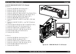
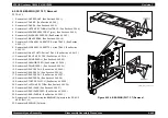
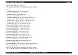
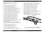
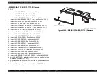
4.2.20.42 SHAFT FEED 2 (PL17.3.22) Removal
TRAY 2
1. Remove the COVER FRONT. (See Section 4.2.20.1.)
2. Remove the COVER R. (See Section 4.2.20.2.)
3. Remove the COVER L. (See Section 4.2.20.3.)
4. Remove the CHUTE ASSY TURN. (See Section 4.2.20.4.)
5. Remove the HARNESS ASSY FDR 2T (gray). (See Section 4.2.20.5.)
6. Remove the DRIVE ASSY FEEDER. (See Section 4.2.20.7.)
7. Remove the PWBA FEEDER. (See Section 4.2.20.10.)
8. Remove the GUIDE ASSY CASSETTE R. (See Section 4.2.20.11.)
9. Remove the GUIDE ASSY CASSETTE L. (See Section 4.2.20.12.)
10. Remove the LINK ACTUATOR. (See Section 4.2.20.13.)
11. Remove the PICK UP ASSY TR2. (See Section 4.2.20.14.)
12. Remove the SPRING FEED H. (See Section 4.2.20.23.)
13. Remove the SOLENOID FEED. (See Section 4.2.20.22.)
14. Remove the SPRING FEED 1. (See Section 4.2.20.24.)
15. Remove the GEAR FEED H2. (See Section 4.2.20.25.)
16. Remove the GEAR FEED 1. (See Section 4.2.20.26.)
17. Remove the GEAR FEED H1. (See Section 4.2.20.27.)
18. Remove the GEAR FEED 2. (See Section 4.2.20.28.)
19. Remove the STOPPER CLUTCH. (See Section 4.2.20.29.)
20. Remove the CLUTCH ASSY TURN. (See Section 4.2.20.30.)
21. Remove the GEAR IDLER. (See Section 4.2.20.31.)
22. Remove the GEAR IDLER FEED. (See Section 4.2.20.32.)
23. Remove the BEARING of the SHAFT FEED 2. (See Section 4.2.20.38.)
24. Shift the SHAFT FEED 2 to the left, pull out it from the shaft hole of the
FRAME ASSY DRIVE (PL17.3.21).
25. Pull out the BEARING SLEEVE (PL17.3.21) to the right from the SHAFT
FEED 2.
26. Remove the E-ring secured in the middle of the SHAFT FEED 2.
Figure 4-160. SENSOR NO PAPER (PL17.3.4) Removal
Содержание AcuLaser C3000 Series
Страница 1: ...EPSON AcuLaserC4000 AcuLaserC4100 AcuLaserC3000 Color Laser Page Printer SEPG01012 SERVICE MANUAL ...
Страница 20: ...C H A P T E R 1 PRODUCTDESCRIPTIONS ...
Страница 71: ...C H A P T E R 2 OPERATINGPRINCIPLES ...
Страница 118: ...C H A P T E R 3 TROUBLESHOOTING ...
Страница 318: ...C H A P T E R 4 DISASSEMBLYANDASSEMBLY ...
Страница 472: ...C H A P T E R 5 ADJUSTMENT ...
Страница 477: ...C H A P T E R 6 MAINTENANCE ...
Страница 491: ...C H A P T E R 7 AcuLaserC4100 ...
Страница 548: ......
Страница 549: ......
Страница 550: ......
Страница 551: ......
Страница 552: ......
Страница 553: ......
Страница 554: ......
Страница 555: ...C H A P T E R 8 AcuLaserC3000 ...
Страница 579: ...Model AcuLaser C3000 Board C569MAIN BOARD Sheet 1 of 5 Rev B ...
Страница 580: ...Model AcuLaser C3000 Board C569MAIN BOARD Sheet 2 of 5 Rev B ...
Страница 581: ...Model AcuLaser C3000 Board C569MAIN BOARD Sheet 3 of 5 Rev B ...
Страница 582: ...Model AcuLaser C3000 Board C569MAIN BOARD Sheet 4 of 5 Rev B ...
Страница 583: ...Model AcuLaser C3000 Board C569MAIN BOARD Sheet 5 of 5 Rev B ...
Страница 584: ...C H A P T E R 9 APPENDIX ...
Страница 617: ...EPSON AcuLaser C4000 C4100 C3000 Revision F Appendix Wiring Diagrams 9 602 Figure 9 6 P J Location 6 ...
Страница 644: ...EPSON AcuLaser C4000 C4100 C3000 Revision F Appendix Wiring Diagrams and Signal Information 9 629 ...
Страница 674: ......
Страница 675: ......
Страница 676: ......
Страница 677: ......
Страница 678: ......
Страница 679: ......
Страница 680: ......


