EPSON AcuLaser C4000/C4100/C3000
Revision F
Troubleshooting
Level 2 FIP
3-148
9
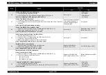
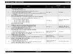
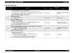
PWBA MCU & HVPS (PL15.1.2) power supply circuit continuity
1. Disconnect the P/J11 connector from the PWBA MCU & HVPS.
2. Check the continuity between P11-18 <=> P18-1.
Is there continuity between P11-18 <=> P18-1?
Go to step 10.
Replace the PWBA MCU &
HVPS. (Refer to Ch4-4.2.18.1)
10
Harness Assy DRV 1 (PL15.2.2) continuity
1. Remove the PHD Assy (PL11.1.3).
2. Measure the voltage between P41-23 <=> P/J41-22/21 of the PWB Drive (PL15.1.15).
Is there 3.3V DC between P/J41-23 <=> P/J41-22/21?
Replace the Harness Assy
DRV1 (PL15.2.2).
Go to step 11.
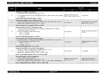
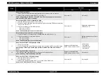
11
PWB Drive (PL15.1.15) power supply circuit continuity
1. Remove the PHD Assy (PL11.1.3).
2. Measure the voltage between P61-6 <=> P/J61-5 of the PWB Drive (PL15.1.15).
Is there 3.3V DC between P/J61-6 <=> P/J61-5?
Replace the PWB Drive.
(Refer to Ch4-4.2.18.5)
Go to step 12.
12
Harness Assy LVNC (PL15.2.1) continuity
1. Remove the PHD Assy (PL11.1.3).
2. Measure the voltage between P165-3 <=> P/J165-4 of the LVPS (PL15.1.10).
Is there 3.3V DC between P/J165-3 <=> P/J165-4?
Replace the Harness Assy
LVNC (PL15.2.1).
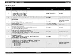
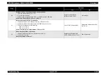
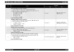
13
Sensor Regi (PL10.1.20)
1. Replace the Sensor Regi. (Refer to Ch4-4.2.13.2)
2. Carry out a test print.
Does the problem still occur?
• With the tool:
Go to step 14.
• Without the tool:
Go to step 15.
Problem solved.
14
Clutch Regi (PL10.1.12) check
Use the Clutch Regi diagnosis tool to carry out a Digital Input Test.
The interlock switch should be closed.
Is the Clutch Regi functioning normally?
Go to step 19.
Go to step 15.
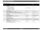
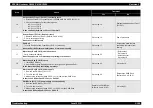
15
Clutch Regi (PL10.1.12) resistance check
Disconnect the J18 connector from the Clutch Regi.
Is the resistance 200
Ω
between J18-4 <=> J18-5?
Go to step 16.
Replace the Clutch Regi.
(Refer to Ch4-4.2.13.1)
16
Clutch Regi (PL10.1.12) power supply
1. Remove the PHD Assy (PL11.1.3).
2. Close the Interlock SW.
3. Measure the voltage between connectors P/J41-17/18 <=> P41-19/20 of the PWB Drive
(PL15.1.15).
Is there +24V DC between P41-17/18 <=> P41-19/20?
Go to step 17.
Go to step 20.
Step
Check
Treatment
Yes
No
Содержание AcuLaser C3000 Series
Страница 1: ...EPSON AcuLaserC4000 AcuLaserC4100 AcuLaserC3000 Color Laser Page Printer SEPG01012 SERVICE MANUAL ...
Страница 20: ...C H A P T E R 1 PRODUCTDESCRIPTIONS ...
Страница 71: ...C H A P T E R 2 OPERATINGPRINCIPLES ...
Страница 118: ...C H A P T E R 3 TROUBLESHOOTING ...
Страница 318: ...C H A P T E R 4 DISASSEMBLYANDASSEMBLY ...
Страница 472: ...C H A P T E R 5 ADJUSTMENT ...
Страница 477: ...C H A P T E R 6 MAINTENANCE ...
Страница 491: ...C H A P T E R 7 AcuLaserC4100 ...
Страница 548: ......
Страница 549: ......
Страница 550: ......
Страница 551: ......
Страница 552: ......
Страница 553: ......
Страница 554: ......
Страница 555: ...C H A P T E R 8 AcuLaserC3000 ...
Страница 579: ...Model AcuLaser C3000 Board C569MAIN BOARD Sheet 1 of 5 Rev B ...
Страница 580: ...Model AcuLaser C3000 Board C569MAIN BOARD Sheet 2 of 5 Rev B ...
Страница 581: ...Model AcuLaser C3000 Board C569MAIN BOARD Sheet 3 of 5 Rev B ...
Страница 582: ...Model AcuLaser C3000 Board C569MAIN BOARD Sheet 4 of 5 Rev B ...
Страница 583: ...Model AcuLaser C3000 Board C569MAIN BOARD Sheet 5 of 5 Rev B ...
Страница 584: ...C H A P T E R 9 APPENDIX ...
Страница 617: ...EPSON AcuLaser C4000 C4100 C3000 Revision F Appendix Wiring Diagrams 9 602 Figure 9 6 P J Location 6 ...
Страница 644: ...EPSON AcuLaser C4000 C4100 C3000 Revision F Appendix Wiring Diagrams and Signal Information 9 629 ...
Страница 674: ......
Страница 675: ......
Страница 676: ......
Страница 677: ......
Страница 678: ......
Страница 679: ......
Страница 680: ......


