EPSON AcuLaser C4000/C4100/C3000
Revision F
Disassembly and Assembly
Disassembly Assembly Procedures
4-390
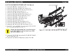
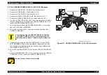
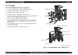
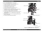
7. Disconnect the connector (P/J51) on the PWB DRIVE (PL15.1.15) from the
right side surface of the printer body.
8. Disconnect the connector (P/J144) on the PWB EEPROM (PL12.1.8) from
the left side surface of the printer body.
9. Disconnect the connectors (P/J5020, P/J5030, P/J5011) on the HVPS
SUB (PL12.1.9) from the left side surface of the printer body.
10. Disconnect the P/J71 connector on the BRACKET CONNECTOR
(PL15.1.16) of the HARNESS ASSY FRONT1 (PL15.2.7), and release
from the clamp.
11. Release the 2 hooks securing the GEAR SLIDE (PL12.3.14) to the left side
surface of the printer body, and remove the GEAR SLIDE.
12. Remove the RACK V (PL12.3.13) from the printer body.
13. Remove the 8 screws securing the HOLDER TCRU ASSY UNIT to the
printer body (4 right side screws: gold, 6mm; 1 upper side screw: gold,
tapped, 10mm; 1 left side screw: gold, 6mm; 2 left side screws: gold,
tapped, 10 mm Earth wire is attached with lower screw.).
14. Remove the HOLDER TCRU ASSY UNIT from the printer body.
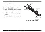
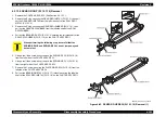
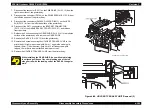
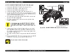
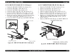
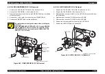
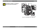
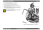
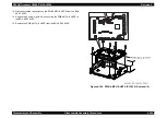
Figure 4-88. HOLDER TCRU ASSY UNIT Removal (3)
When installing the GEAR SLIDE, do so while maintaining
the aligned positions of the sharp leading end of the left
side gear rail with the leading end of the RACK V triangular
mark.
HANABI_BE_CHAP03_060FB
Содержание AcuLaser C3000 Series
Страница 1: ...EPSON AcuLaserC4000 AcuLaserC4100 AcuLaserC3000 Color Laser Page Printer SEPG01012 SERVICE MANUAL ...
Страница 20: ...C H A P T E R 1 PRODUCTDESCRIPTIONS ...
Страница 71: ...C H A P T E R 2 OPERATINGPRINCIPLES ...
Страница 118: ...C H A P T E R 3 TROUBLESHOOTING ...
Страница 318: ...C H A P T E R 4 DISASSEMBLYANDASSEMBLY ...
Страница 472: ...C H A P T E R 5 ADJUSTMENT ...
Страница 477: ...C H A P T E R 6 MAINTENANCE ...
Страница 491: ...C H A P T E R 7 AcuLaserC4100 ...
Страница 548: ......
Страница 549: ......
Страница 550: ......
Страница 551: ......
Страница 552: ......
Страница 553: ......
Страница 554: ......
Страница 555: ...C H A P T E R 8 AcuLaserC3000 ...
Страница 579: ...Model AcuLaser C3000 Board C569MAIN BOARD Sheet 1 of 5 Rev B ...
Страница 580: ...Model AcuLaser C3000 Board C569MAIN BOARD Sheet 2 of 5 Rev B ...
Страница 581: ...Model AcuLaser C3000 Board C569MAIN BOARD Sheet 3 of 5 Rev B ...
Страница 582: ...Model AcuLaser C3000 Board C569MAIN BOARD Sheet 4 of 5 Rev B ...
Страница 583: ...Model AcuLaser C3000 Board C569MAIN BOARD Sheet 5 of 5 Rev B ...
Страница 584: ...C H A P T E R 9 APPENDIX ...
Страница 617: ...EPSON AcuLaser C4000 C4100 C3000 Revision F Appendix Wiring Diagrams 9 602 Figure 9 6 P J Location 6 ...
Страница 644: ...EPSON AcuLaser C4000 C4100 C3000 Revision F Appendix Wiring Diagrams and Signal Information 9 629 ...
Страница 674: ......
Страница 675: ......
Страница 676: ......
Страница 677: ......
Страница 678: ......
Страница 679: ......
Страница 680: ......

