EPSON AcuLaser C4000/C4100/C3000
Revision F
Troubleshooting
Level 2 FIP
3-181
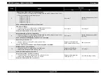
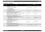
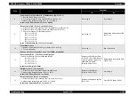
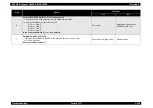
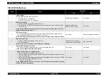
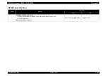
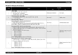
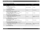
FIP-25 Black Toner Empty
Step
Check
Treatment
Yes
No
1
Initial setting
Do the following checks show a problem?
• Sensor Toner Low (PL12.2.9) installation
• Toner Cartridge installation
• Toner Motor installation
Reinstall applicable parts.
Go to step 2.
2
Toner Cartridge (K) (PL12.1.4) check
1. Replace the Toner Cartridge (K).
2. Turn On the power.
Does an error occur even when a new Cartridge is installed?
Go to step 3.
End of procedure
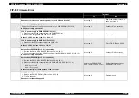
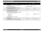
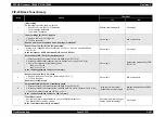
3
Sensor Toner Low (K) (PL12.2.9) signal check
Measure the voltage between connectors P/J51-36 <=> P/J51-35 of the PWB Drive
(PL15.1.15).
Is the resi 0.2V DC between P/J51-36 <=> P/J51-35?
Go to step 6.
Go to step 4.
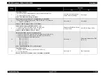
4
Harness Assy TNR (PL12.1.6) continuity check
1. Disconnect the P/J51 connector from the PWB Drive (PL15.1.15).
2. Disconnect the P/J444 connector from the Sensor Toner Low (PL12.2.9) (C).
3. Check the continuity for the following lines.
J444-2 <=> J51-36
J444-3 <=> J51-35
Is the continuity between J444 <=> J51 normal?
Go to step 5.
Replace the Harness Assy TNR
(PL12.1.6).
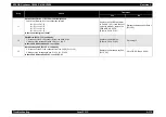
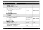
5
Sensor Toner Low (PL12.2.9) check
1. Replace the Sensor Toner Low. (Refer to Ch4-4.2.15.7)
2. Turn On the power.
Does the error still occur?
Go to step 6.
End of procedure
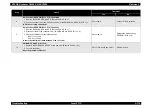
6
Harness Assy DRV 2 (PL15.2.3) continuity check
1. Disconnect the P/J42 connector from the PWB Drive (PL15.1.15).
2. Disconnect the P/J12 connector from the PWBA MCU & HVPS. (Refer to Ch4-4.2.18.1)
3. Check the continuity between J12-24 <=> J42-7.
Is the continuity between J12-24 <=> J42-7 normal?
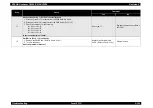
• With the tool: Go to step 7.
• Without the tool: Go to step 8.
Replace the Harness Assy DRV 2
(PL15.2.3).
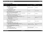
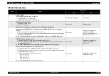
7
Toner Motor check
Use the Toner Motor diagnosis tool to carry out a Digital Output Test.
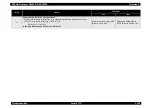
The Interlock SW should be closed.
Is the Toner Motor functioning normally?
Check the toner mixing Auger
and the Gears for damage.
Go to step 8.
Содержание AcuLaser C3000 Series
Страница 1: ...EPSON AcuLaserC4000 AcuLaserC4100 AcuLaserC3000 Color Laser Page Printer SEPG01012 SERVICE MANUAL ...
Страница 20: ...C H A P T E R 1 PRODUCTDESCRIPTIONS ...
Страница 71: ...C H A P T E R 2 OPERATINGPRINCIPLES ...
Страница 118: ...C H A P T E R 3 TROUBLESHOOTING ...
Страница 318: ...C H A P T E R 4 DISASSEMBLYANDASSEMBLY ...
Страница 472: ...C H A P T E R 5 ADJUSTMENT ...
Страница 477: ...C H A P T E R 6 MAINTENANCE ...
Страница 491: ...C H A P T E R 7 AcuLaserC4100 ...
Страница 548: ......
Страница 549: ......
Страница 550: ......
Страница 551: ......
Страница 552: ......
Страница 553: ......
Страница 554: ......
Страница 555: ...C H A P T E R 8 AcuLaserC3000 ...
Страница 579: ...Model AcuLaser C3000 Board C569MAIN BOARD Sheet 1 of 5 Rev B ...
Страница 580: ...Model AcuLaser C3000 Board C569MAIN BOARD Sheet 2 of 5 Rev B ...
Страница 581: ...Model AcuLaser C3000 Board C569MAIN BOARD Sheet 3 of 5 Rev B ...
Страница 582: ...Model AcuLaser C3000 Board C569MAIN BOARD Sheet 4 of 5 Rev B ...
Страница 583: ...Model AcuLaser C3000 Board C569MAIN BOARD Sheet 5 of 5 Rev B ...
Страница 584: ...C H A P T E R 9 APPENDIX ...
Страница 617: ...EPSON AcuLaser C4000 C4100 C3000 Revision F Appendix Wiring Diagrams 9 602 Figure 9 6 P J Location 6 ...
Страница 644: ...EPSON AcuLaser C4000 C4100 C3000 Revision F Appendix Wiring Diagrams and Signal Information 9 629 ...
Страница 674: ......
Страница 675: ......
Страница 676: ......
Страница 677: ......
Страница 678: ......
Страница 679: ......
Страница 680: ......


