EPSON AcuLaser C4000/C4100/C3000
Revision F
Disassembly and Assembly
Disassembly Assembly Procedures
4-434
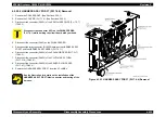
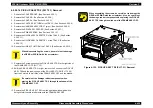
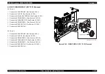
4.2.20.20 SWITCH ASSY SIZE (PL17.2.7) Removal
TRAY 2
1. Remove the COVER FRONT. (See Section 4.2.20.1.)
2. Remove the COVER R. (See Section 4.2.20.2.)
3. Remove the CHUTE ASSY TURN. (See Section 4.2.20.4.)
4. Remove the DRIVE ASSY FEEDER. (See Section 4.2.20.7.)
5. Remove the PWBA FEEDER. (See Section 4.2.20.10.)
6. Remove the GUIDE ASSY CASSETTE R. (See Section 4.2.20.11.)
7. Remove the 1 screw (gold, tapped, 8mm) securing the SWITCH ASSY
SIZE fram upside to the GUIDE ASSY CASSETTE R (PL17.2.2), and
remove the SWITCH ASSY SIZE.
TRAY 3
1. Remove the COVER FRONT. (See Section 4.2.20.1.)
2. Remove the COVER R. (See Section 4.2.20.2.)
3. Remove the CHUTE ASSY TURN. (See Section 4.2.20.4.)
4. Remove the GUIDE ASSY CASSETTE R. (See Section 4.2.20.11.)
5. Remove the 1 screw (gold, tapped, 8mm) securing the SWITCH ASSY
SIZE fram upside to the GUIDE ASSY CASSETTE R (PL17.2.2), and
remove the SWITCH ASSY SIZE.
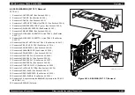
Figure 4-138. SWITCH ASSY SIZE (PL17.2.7) Removal
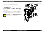
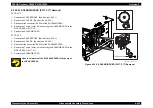
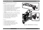
4.2.20.21 STOPPER CST (PL17.2.4) Removal
1. Remove CASSETTE TRAY, and any others of the type that can be
withdrawn, by pulling them straight out then tilting them up to take them all
the way out.
2. Remove the 1 screw (gold, tapped, 8mm) securing the STOPPER CST to
the GUIDE CASSETTE L (PL17.2.3), and remove the STOPPER CST.
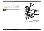
Figure 4-139. STOPPER CST (PL17.2.4) Removal
C H E C K
P O I N T
The following steps is a common to the TRAY 2 and the
TRAY 3.
Содержание AcuLaser C3000 Series
Страница 1: ...EPSON AcuLaserC4000 AcuLaserC4100 AcuLaserC3000 Color Laser Page Printer SEPG01012 SERVICE MANUAL ...
Страница 20: ...C H A P T E R 1 PRODUCTDESCRIPTIONS ...
Страница 71: ...C H A P T E R 2 OPERATINGPRINCIPLES ...
Страница 118: ...C H A P T E R 3 TROUBLESHOOTING ...
Страница 318: ...C H A P T E R 4 DISASSEMBLYANDASSEMBLY ...
Страница 472: ...C H A P T E R 5 ADJUSTMENT ...
Страница 477: ...C H A P T E R 6 MAINTENANCE ...
Страница 491: ...C H A P T E R 7 AcuLaserC4100 ...
Страница 548: ......
Страница 549: ......
Страница 550: ......
Страница 551: ......
Страница 552: ......
Страница 553: ......
Страница 554: ......
Страница 555: ...C H A P T E R 8 AcuLaserC3000 ...
Страница 579: ...Model AcuLaser C3000 Board C569MAIN BOARD Sheet 1 of 5 Rev B ...
Страница 580: ...Model AcuLaser C3000 Board C569MAIN BOARD Sheet 2 of 5 Rev B ...
Страница 581: ...Model AcuLaser C3000 Board C569MAIN BOARD Sheet 3 of 5 Rev B ...
Страница 582: ...Model AcuLaser C3000 Board C569MAIN BOARD Sheet 4 of 5 Rev B ...
Страница 583: ...Model AcuLaser C3000 Board C569MAIN BOARD Sheet 5 of 5 Rev B ...
Страница 584: ...C H A P T E R 9 APPENDIX ...
Страница 617: ...EPSON AcuLaser C4000 C4100 C3000 Revision F Appendix Wiring Diagrams 9 602 Figure 9 6 P J Location 6 ...
Страница 644: ...EPSON AcuLaser C4000 C4100 C3000 Revision F Appendix Wiring Diagrams and Signal Information 9 629 ...
Страница 674: ......
Страница 675: ......
Страница 676: ......
Страница 677: ......
Страница 678: ......
Страница 679: ......
Страница 680: ......

