Micropilot M FMR 240 with PROFIBUS PA
Wiring
E Hauser
29
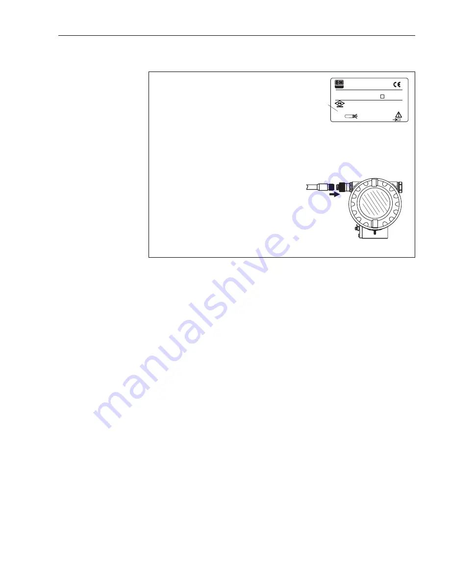
Wiring with M12 connector
L00-FMR230xx-04-00-00-en-004
4.1.1
Cable specification PROFIBUS
Twisted, screened pairs must be used. The following specification must be met for
explosion hazardous application (EN 50 020, FISCO model):
•
Loop-resistance (DC): 15…150
Ω
/km,
•
Specific inductance: 0.4…1 mH/km,
•
Specific capacitance: 80…200 nF/km
The following cable types can be used, for example
Non-Ex-area:
•
Siemens 6XV1 830-5BH10 (black),
•
Kerpen CEL-PE/OSCR/PVC/FRLA FB-02YS(ST)YFL (grey)
•
Belden 3076F (orange)
Ex-area:
•
Siemens 6XV1 830-5AH10 (blue),
•
Belden 3076F, Kerpen CEL-PE/OSCR/PVC/FRLA FB-02YS(ST)YFL (blue)
1
-
"
Ser.-No.:
Order Code:
D00899-A
t >85°C
x = if modification
see sep. label
Dat./Insp.:
PN max.
TAntenne max.
°C
T >70°C :
A
MICROPILOT M
HAUSER
FCC ID LCG FMR2
INT. SAFE (entity) and
T-Code per control drawing
Profibus PA
NEMA 4X
Assembled
in
USA
Patents
2
3
Before connection please note the following:
PROFIBUS devices are marked on the nameplate (1). The
voltage is determined by the PROFIBUS PA standard and the
desired safety concept. (see chapter 4.3).
Connect potential matching line to transmitter earth terminal
before connecting up the device.
Tighten the locking screw:
It forms the connection between the antenna and the housing
earth potential.
●
●
●
When you use the measuring system in hazardous areas, make sure you comply with
national standards and the specifications in the safety instructions (XA’s).
Make sure you use the specific cable gland.
On devices supplied with a certificate, the explosion protection
is designed as follows:
Housing F12/F23 - EEx ia:
Power supply must be intrinsically safe.
The electronics and the current output are galvanically
separated from the antenna circuit.
●
●
Caution!
The Micropilot M is connected as follows:
Insert plug (2) into bushing (3).
Screw firmly
Ground the device according to the desired safety concept.
●
●
●


