background image

ROC364 Instruction Manual  

3-13  

Input and Output Modules 

Rev Jun/05 

3.4.9  Discrete Output Relay Module 

A schematic representation of the field wiring connections to the output circuit of the Discrete Output 
Relay module displays in Figure 3-15. 


NOTE:

 The Discrete Output Relay module is designed to operate only with discrete devices 

having their own power source. The module will be inoperative with non-powered devices. 

The Discrete Output Relay module operates by providing both normally-closed and normally-open 
contacts to a field device. Normally-closed contacts use terminals B and C, and normally-open contacts 
use terminals A and B. ROCLINK configuration software controls the status of the contacts (open or 
closed). 

There are two versions of the DO Relay module. The 12 volts version (which has a 12 volts energizing 
coil) must be used when the ROC input voltage is a nominal 12 volts dc, and the 24 volts version (which 
has a 24 volts energizing coil) must be used when the ROC input voltage is a nominal 24 volts dc. 

TERMINAL A CONNECTION TO BE MADE FOR NORMALLY OPEN APPLICATIONS
TERMINAL B IS COMMON
TERMINAL C CONNECTION TO BE MADE FOR NORMALLY CLOSED APPLICATIONS

V

O

= VOLTAGE FROM DISCRETE DEVICE = 0 TO 30 VDC OR 0 TO 115 VAC, 5 A MAX

DO RLY

V

S

DOC0147A

CONTROL

COM

NC

NO

C

B

A

DISCRETE DEVICE

SELF-POWERED

+

V

O


Figure 3-15. Discrete Output Relay Module Field Wiring 

3.4.10  Pulse Input Source Module 

A schematic representation of the field wiring connections to the input circuit of the Pulse Input  
Source module is shown in Figure 3-16. 


The Pulse Input Source module is designed to operate only with non-powered discrete devices, 
such as “dry” relay contacts or isolated solid-state switches. Use of the module with powered 
devices may cause improper operation or damage to occur. 

The Pulse Input Source module provides a voltage across terminals B and C that is derived from internal 
voltage source V

s

. When a field device, such as a set of relay contacts, is connected across terminals B 

and C, the opening and closing of the contacts causes current to either flow or not flow between V

s

 and 

ground at terminal C. 

This interrupted, or pulsed current flow is counted and accumulated by the PI Source module, which 
provides the accumulated count to the ROC electronics upon request. 

Содержание ROC364

Страница 1: ...Flow Computer Division Website www EmersonProcess com flow Form A4193 Part Number D301060X012 June 2005 ROC364 REMOTE OPERATIONS CONTROLLER Instruction Manual ...

Страница 2: ...a trademark and service mark of Emerson Electric Co All other marks are the property of their respective owners Fisher Controls International Inc 1992 2005 All rights reserved Printed in the U S A While this information is presented in good faith and believed to be accurate Fisher Controls does not guarantee satisfactory results from reliance upon such information Nothing contained herein is to be...

Страница 3: ...onnecting the MCU to Wiring 2 9 2 5 Troubleshooting and Repair 2 12 2 6 ROC364 Specifications 2 20 Section 3 Input and Output Modules 3 1 3 1 Scope 3 1 3 2 Product Descriptions 3 1 3 3 Initial Installation and Setup 3 5 3 4 Connecting the I O Modules to Wiring 3 5 3 5 Troubleshooting and Repair 3 21 3 6 Removal Addition and Replacement Procedures 3 28 3 7 I O Module Specifications 3 30 Section 4 C...

Страница 4: ... and Repair A 2 A 4 Lightning Protection Module Specifications A 3 Appendix B Local Display Panel B 1 B 1 Product Description B 1 B 2 Installation B 2 B 3 Operation B 4 B 4 Troubleshooting and Repair B 22 B 5 Local Display Panel Specifications B 23 Appendix C I O Simulation C 1 C 1 Analog Outputs to Analog Inputs C 1 C 2 Analog Outputs to Ammeter or Voltmeter C 2 C 3 Discrete Outputs to Discrete I...

Страница 5: ...6 1 6 Startup and Operation 1 9 1 2 Manual Contents This manual contains the following sections Section 2 details the Master Controller Unit MCU I O Module Rack wiring troubleshooting and specifications Section 3 provides information and specifications for the I O modules Section 4 provides details and specifications for the communications cards Appendix A describes the optional Lightning Protecti...

Страница 6: ...upted service If trouble is experienced with this equipment dial up modem for repair or warranty information please contact Emerson Process Management Flow Computer Division 641 754 2578 If the equipment is causing harm to the telephone network the telephone company may request that you disconnect the equipment until the problem is resolved 1 3 Product Overview The ROC364 is a microprocessor based...

Страница 7: ...e application location ground conditions climate and accessibility only generalized guidelines can be provided in this document ROC364 SYSTEM STATUS GND AUX PWR OUT 1 DC PWR IN AUX PWR OUT 2 AUX OUT 2 AUX OUT 1 POWER OPERATOR INTERFACE COM2 COM1 DISPLAY ROC REMOTE OPERATIONS CONTROLLER RAM MEMORY EXPANSION 3 2 1 F3 F2 F1 AUX OUT 2 5A 32 VDC 5A 32 VDC AUX OUT 1 POWER 2A S B 32 VDC FLASHPAC 1 2 3 4 ...

Страница 8: ...pe flanges and hazardous area classifications Ensure that all code requirements are met Locate the ROC to minimize the length of signal and power wiring By code line power wiring must not cross meter runs Solar panels must face due South not magnetic South in the northern hemisphere and due North not magnetic North in the southern hemisphere Make sure nothing blocks the sunlight during any part of...

Страница 9: ...nuous reliable operation Information contained in the ROC ROC Accessories Instruction Manual Form 4637 can assist in determining the solar panel and battery requirements A site may have additional power requirements for radios repeaters and other monitoring devices Power supply and converter accessories can minimize the number of separate power sources required for an installation The ROC364 can o...

Страница 10: ...es the requirements for either line or solar power supplies Table 1 1 and Table 1 2 provide information to assist in determining power supply requirements Table 1 1 lists the power consumption of the ROC364 and the optional devices available for it Include in the power consumption calculations of all device relays meters solenoids radios and other devices that receive DC power from the ROC excludi...

Страница 11: ...olumn 5 Repeat the procedure for all other I O channels used 6 Total the values in the I O Modules Sub Total column in Table 1 2 7 Enter the I O Modules Total value in Table 1 1 8 Calculate the Radio Power Consumption total Refer to Section 1 5 2 Determining Radio Power Consumption on page 1 8 9 Enter the Radio Power Consumption Total value in Table 1 1 10 Calculate Total power consumption in Tabl...

Страница 12: ... spent in the upper half of the operating range 2 The Pmax amount includes any power drawn by a ROC powered field device such as a transmitter 1 5 2 Determining Radio Power Consumption In determining power requirements for radios 1 Estimate the Duty Cycle for the radio The Duty Cycle is the percentage of time the radio is transmitting TX For example if a radio is transmitting 1 second out of every...

Страница 13: ...convert PSF to current consumption in amps ISF divide PSF by the system voltage V either 12 volts or 24 volts ISF PSF V _____ Amps 1 6 Startup and Operation Before starting up the ROC perform the following checks to ensure the unit is properly installed Make sure the enclosure has a good earth ground Make sure the MCU is grounded at the power input connector Make sure all I O module racks are grou...

Страница 14: ...ke up to 5 seconds If any of the indicators do not light refer to the Troubleshooting details in Section 2 for possible causes 1 6 2 Operation Once startup is successful configure the ROC to meet the requirements of the application The appropriate ROCLINK configuration software user manual describes in detail the procedure for configuring the ROC Once the ROC is configured and I O is calibrated it...

Страница 15: ...and Repair 2 12 2 6 ROC364 Specifications 2 20 2 2 Product Description The following subsections describe components of the ROC364 including the Master Controller Unit FlashPACs Diagnostic Analog Inputs Auxiliary Discrete Outputs I O Module Rack and Backplate 2 2 1 Master Controller Unit The Master Controller Unit MCU is the brain of the ROC Figure 2 1 displays MCU The MCU consists of NEC V25 micr...

Страница 16: ...rface connector provides direct communications between the ROC and the serial port of an operator interface such as a laptop to provide access to the functionality of the ROC The Display connector links the MCU to an optional Local Display Panel LDP also called a Liquid Crystal Display LCD panel The LDP provides local monitoring of I O and database parameters using ROCLINK configuration software L...

Страница 17: ...e FlashPAC module contains the operating system the applications firmware and communications protocol as well as memory storage for history logs and user programs A FlashPAC module contains 512 kilobytes of flash read only memory ROM and 512 kilobytes of battery backed Static Random Access Memory SRAM A FlashPAC module is required for the ROC to operate Back up power for the RAM is provided by a s...

Страница 18: ...numbers NOTE The version may have been updated by a download of upgrade firmware into the module so the label on the actual FlashPAC module might not be accurate Table 2 1 ROC Memory Map Memory Location FlashPAC Usage 00000 to 1FFFF Base RAM Alarm Log Event Log and such 20000 to 3FFFF RAM in FlashPAC History Data Area part is for scratch pad memory in FlashPAC 40000 to 5FFFF RAM in FlashPAC Histor...

Страница 19: ...alog Inputs Analog Outputs and Pulse Inputs A minimum of one rack is required for any ROC connected to field I O and a maximum of four racks can be accommodated The first rack plugs directly into the I O module rack connector on the bottom edge of the MCU Additional racks plug into each other 1 2 3 4 8 7 6 5 9 14 15 16 13 12 11 10 A B C C B A C B A C B A C B A C B A C B A C B A A B C A B C A B C A...

Страница 20: ...modate the indicated number of I O racks one rack two racks and three or four racks Refer to Figure 2 4 for dimensions of the various backplates DIM A DIM C DIM B DIM D DIM G MOUNTING STUD SIZE DIM F DIM E DOC0243A Figure 2 4 Backplate and Mounting Dimensions Maximum I O Points DIM 16 32 64 A 12 40 11 60 11 25 B 11 34 21 46 28 58 C 13 34 13 00 12 25 D 13 12 22 26 29 38 E 3 94 3 94 4 06 F 38 38 50 ...

Страница 21: ...sure that the components selected are labeled for use in such areas Change components only in an area known to be non hazardous Performing these procedures in a hazardous area could result in personal injury or property damage To add I O modules refer to Section 3 To add a communications card refer to Section 4 To install accessories for use with the ROC refer to the ROC ROC Accessories Instructio...

Страница 22: ...Jumpers in the MCU The MCU board contains a set of three jumpers to select the nominal input voltage of either 12 or 24 volts The factory default setting is for 12 volt operation Equipment and Tools Required None To access the jumpers proceed as follows 1 Remove the screws holding the upper MCU cover in place and lift off the cover 2 Unplug any terminal blocks connectors and FlashPACs 3 Remove the...

Страница 23: ...losest to the I O terminals 4 Carefully insert the module in the socket and press it in firmly but gently to seat the module The module should move inward slightly Verify that the module is seated in the connector by gently lifting up on the module If it comes out easily repeat the process 5 Carefully position the retainer over the FlashPAC and tighten the thumbscrews Make sure that the sloped sur...

Страница 24: ...he ROC to a DC power source Before making connections make sure the voltage selection jumpers are in the proper position for the voltage being used and the hook up polarity is correct Refer to Section 2 3 3 Setting Voltage Jumpers in the MCU on page 2 8 The input power DC PWR IN is fused at 2 amps by slow blow fuse F1 which is accessible through the front panel and by a 3 amp fuse located on the M...

Страница 25: ...devices using several different formats and protocols Connectors located on the front panel of the ROC provide both Operator Interface and data communications The Local Operator Interface LOI connector is a serial EIA 232 RS 232 port for communications to a configuration and monitoring device This device is typically a personal computer A null modem cable wires to pins 2 3 and 5 with the wires bet...

Страница 26: ... IBM compatible personal computer ROCLINK configuration software Digital multimeter Fluke 8060A or equivalent 2 5 1 LED Indicators The Light emitting diode LED indicators located on the front panel of the MCU give a first level indication of the operation of the ROC Figure 2 7 shows the location of the indicators and Table 2 2 describes them The primary indicator that the MCU is operating normally...

Страница 27: ...ther data stored in RAM User programs cannot be saved out of the ROC Reload user programs from their original disk files as instructed in the ROCLINK for Windows Configuration Software User Manual Form A6091 or the ROCLINK 800 Configuration Software User Manual Form A6121 When installing devices in a hazardous area make sure each device is labeled for use in such areas Procedures involving switchi...

Страница 28: ...eter to check for continuity To remove fuses F1 F2 or F3 for inspection or replacement proceed as follows 1 Disconnect the ROC from its power source 2 Insert a screwdriver into the slot in the fuse holder cap and rotate counterclockwise 1 4 turn 3 Remove the screwdriver The cap and fuse will spring out Remove the fuse from the cap Reverse steps 1 2 and 3 to install the fuse Fuse F4 is soldered to ...

Страница 29: ...municating with ROCLINK configuration software COM1 COM2 COM3 or COM4 displays in the lower right corner of the screen 2 5 6 Verifying RAM Equipment Required Personal computer with ROCLINK configuration software installed To detect bad RAM 1 Connect the ROC to ROCLINK configuration software 2 Select ROC Information Other Information tab and verify that RAM Installed is labeled PRESENT The problem ...

Страница 30: ...splays to their default values This reset sets the FST run flags to zero clears all Alarm and Event Logs and clears all User Programs NOTE If your ROC is semi functional refer to Section 2 5 2 RAM Backup Procedure on page 2 13 before removing power from your ROC 1 Connect your ROC to a computer running ROCLINK configuration software 2 Select Utilities Download User Programs or User Program Adminis...

Страница 31: ...g connector Do not attempt to straighten bent pins instead replace the FlashPAC 4 Align the key on the FlashPAC socket with the key of the MCU socket Carefully insert the FlashPAC module in the socket and press it in firmly but gently to seat the FlashPAC The FlashPAC should move inward slightly Verify that the FlashPAC is seated into the connector by gently lifting up on the FlashPAC If it comes ...

Страница 32: ...g in 3 Remove the screws from the front cover of the ROC 4 Remove the screw from the communications cards if necessary 5 Remove the communications cards 6 Remove the old battery from the other battery socket B1 by sliding the hold down clip to one side and lifting the battery from the MCU board If the clip does not readily rotate you may need to loosen the screw that secures the hold down clip 7 I...

Страница 33: ... screws Then lift the MCU away from the ROC backplate 5 If you are reasonably sure the FlashPAC modules are functioning keep in mind all RAM is normally cleared during factory servicing you can remove them by unscrewing the two thumbscrews of their retainer and gently pulling each one from its socket 6 The MCU must be returned as an assembly the MCU board must remain in the metal case to your loca...

Страница 34: ...R REQUIREMENTS 11 to 16 V dc 12 5 V to start up or 22 to 30 V dc 25 V to start up jumper selectable 1 Watt typical excluding I O power AUXILIARY OUTPUT POWER Input power is software switched to two sets of auxiliary output power terminals Each output fused for 5 A maximum Output voltage is 0 to 2 V dc less than input voltage depending on load I O POWER CONVERTER OPTIONAL Input 11 to 16 V dc 15 mA ...

Страница 35: ...eld I O and a maximum of four racks can be accommodated The first rack plugs directly into the I O module rack connector on the bottom edge of the MCU Additional racks plug into each other The following modules are available Analog Input AI Loop Discrete Output DO Relay Analog Input AI Differential Pulse Input PI Source Analog Input AI Source Pulse Input PI Isolated Analog Output AO Source Slow Pu...

Страница 36: ... current or voltage input from externally powered devices and provides electrical isolation from the ROC power supplies 3 2 2 Analog Input Source Module The Analog Input Source AI Source module monitors current loop or voltage output devices The Analog Input Source module provides a regulated 10 volts source for powering a device usually a low power transmitter and uses a scaling resistor for conv...

Страница 37: ...wered devices The solid state switch is optically isolated from the power supplies in the ROC 3 2 6 Discrete Output Relay Module The Discrete Output Relay DO Relay module provides two sets of dry relay contacts to switch voltages of up to 250 volts ac One set of contacts is normally open and the other set is normally closed Two types of relay modules are available one with a 12 volts dc energizing...

Страница 38: ...ower supplies 3 2 10 RTD Input Module The Resistance Temperature Detector RTD module monitors the temperature signal from an RTD source The module can accommodate one input from a two three or four wire RTD source The active element of an RTD probe is a precision temperature dependent resistor made from a platinum alloy It has a predictable positive temperature coefficient meaning its resistance i...

Страница 39: ...ld wiring terminal block is installed in the socket adjacent to where the I O module was installed If a Lightning Protection Module is to be installed for this I O channel refer to Appendix A 3 3 1 Calibrating an I O Module After an I O module is installed configure and calibrate the associated I O channel using ROCLINK configuration software 3 4 Connecting the I O Modules to Wiring Each I O modul...

Страница 40: ...quirement different from 20 milliamps R1 should be scaled to achieve full scale deflection at 5 volts dc The formula for determining a new value of R1 is given in Figure 3 2 where I Maximum is the upper end of the operating current range such as 0 025 amps for a 0 to 25 milliamps device I ROC POWERED CURRENT LOOP DEVICE I MAXIMUM R1 TO SELECT PROPER VALUE OF R1 VS SOURCE VOLTAGE FROM MODULE 11 TO ...

Страница 41: ...ides the 0 to 5 volts signal into 4095 counts and the last 95 counts being 4001 to 4095 represent overvoltage If you use a 0 to 1 volt input to the converter the resolution is reduced as there are only 800 counts with which to work For field devices with output voltages that exceed 5 volts dc two scaling resistors R1 and R2 are required not supplied Figure 3 5 shows how to connect field devices wi...

Страница 42: ... the field wiring connections to the input circuit of the Analog Input Source module displays in Figure 3 7 and Figure 3 8 The AI Source module normally monitors the voltage output of low voltage transmitters but it can be used for monitoring loop current The module provides source power at terminal A for the loop The Analog Input Source module operates by measuring the voltage across terminals B ...

Страница 43: ...e Module A schematic representation of the field wiring connections to the output circuit of the Analog Output Source module displays in Figure 3 9 and Figure 3 10 The AO Source module can provide either loop current or output voltage to non powered field devices The Analog Output Source module provides a 0 to 5 5 volts output at terminal A and a 0 to 30 milliamps current source output at terminal...

Страница 44: ...etes a circuit which causes a flow of current between Vs and ground at terminal C This current flow is sensed by the DI module which signals the ROC electronics that the relay contacts have closed When the contacts open current flow is interrupted and the DI module signals the ROC electronics that the relay contacts have opened A 10 ohms scaling resistor R1 is supplied by the factory and accommoda...

Страница 45: ...he source or reduce the heat generated in the module due to high source voltage The formula for determining the optimum value of R1 displays in Figure 3 12 For best efficiency R1 should be scaled for a loop current I of 3 milliamps SELF POWERED DISCRETE DEVICE 3 3K N C R1 RW 3 3K LOOP RESISTANCE 4 5K OHMS MAX VO VOLTAGE FROM DISCRETE DEVICE 11 TO 30 VDC I LOOP CURRENT 3 mA TYPICAL TO OPTIMIZE SCAL...

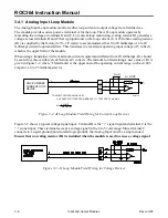
Страница 46: ...ed module is shown in Figure 3 14 NOTE The Discrete Output Isolated module is designed to operate only with discrete devices having their own power source The module is inoperative with non powered devices The Discrete Output Isolated module operates by providing a low or high output resistance to a field device When the field device provides a voltage across terminals A and B of the module curren...

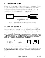
Страница 47: ...ION TO BE MADE FOR NORMALLY OPEN APPLICATIONS TERMINAL B IS COMMON TERMINAL C CONNECTION TO BE MADE FOR NORMALLY CLOSED APPLICATIONS VO VOLTAGE FROM DISCRETE DEVICE 0 TO 30 VDC OR 0 TO 115 VAC 5 A MAX DO RLY VS DOC0147A CONTROL COM NC NO C B A DISCRETE DEVICE SELF POWERED VO Figure 3 15 Discrete Output Relay Module Field Wiring 3 4 10 Pulse Input Source Module A schematic representation of the fie...

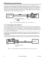
Страница 48: ... circuit of the Pulse Input Isolated module is shown in Figure 3 17 NOTE The Pulse Input Isolated module is designed to operate only with devices having their own power source such as wet relay contacts or two state devices providing an output voltage The module is inoperative with non powered devices The Pulse Input Isolated module operates when a field device provides a voltage across terminals ...

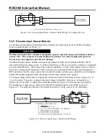
Страница 49: ...internal voltage source Vs When a field device such as a set of relay contacts is connected across terminals B and C the closing of the contacts completes a circuit which causes a flow of current between Vs and ground at terminal C This current flow is sensed by the SPI module which signals the ROC electronics that the relay contacts have closed When the contacts open current flow is interrupted a...

Страница 50: ...s up a flow of current sensed by the module which signals the ROC electronics that the field device is active When the field device no longer provides a voltage current stops flowing and the SPI module signals the ROC electronics that the device is inactive The ROC counts the number of times the current starts flowing and stores the count The ROC checks for the input transition every 50 millisecon...

Страница 51: ... module is isolated reducing the possibility of lightning damage A Lightning Protection Module LPM will not protect the RTD but it helps protect the rack in which the module is installed The RTD module must to be calibrated while disconnected from the RTD probe therefore it may be more convenient to perform calibration before connecting the field wiring However if the field wiring between the ROC ...

Страница 52: ...n table for that probe 1 Connect the decade box as shown in Figure 3 21 2 Set the decade box to the 50 C 58 F resistance value corresponding to the RTD alpha value in Table 3 1 3 Enter the value displayed for Raw A D Input as the value for Adjusted A D 0 using the Analog Inputs configuration screen for the RTD input Refer to ROCLINK Configure I O AI Points Advanced tab 4 Set the decade box to the ...

Страница 53: ...compensate for the resistance of hookup wire used between the probe and RTD module In operation the RTD module subtracts the resistance between terminals B and C from the resistance between terminals A and B The remainder is the resistance of only the active element of the probe This compensation becomes more important as the resistance of the hookup wire increases with distance between the probe ...

Страница 54: ... the ROC to interface with up to ten Highway Addressable Remote Transducer HART devices per I O slot The HART module provides loop source power T on terminal A and two channels for communications on terminals B and C The T power is regulated by a current limit If the power required by all connected HART devices exceeds 40 milliamps more than an average of 4 milliamps each the total number of HART ...

Страница 55: ...mine if the problem is with the field device or the I O module as follows Failure to exercise proper electrostatic discharge precautions such as wearing a grounded wrist strap may reset the processor or damage electronic components resulting in interrupted operations 1 Isolate the field device from the ROC by disconnecting it at the I O module terminal block 2 Connect the ROC to a computer running...

Страница 56: ...w which can result from shorted field wiring or a faulty field device When the value of Filtered EUs is between the low and high readings you can verify the accuracy of the reading by measuring the voltage across scaling resistor Rs Vrs with the multimeter To convert this reading to the filtered EUs value perform the following Filtered EUs Vrs 1 4 Span Low Reading EU where Span High Reading EU Low...

Страница 57: ...w Reading EU values as before Scanning Disabled and observing the field device 3 5 2 2 Check AO Voltage Source Installations Equipment Required Multimeter Personal Computer running ROCLINK configuration software To check operation of the Analog Output module powering a voltage device 1 If the resistance value R of the field device is known measure the voltage drop V across the device and calculate...

Страница 58: ...resistor is being used 3 5 5 Discrete Output Source Module Equipment Required Multimeter Personal Computer running ROCLINK configuration software 1 Place the Discrete Output in manual mode Scanning Disabled using ROCLINK configuration software 2 With the output Status set to Off less than 0 5 volts dc should be measured across pins B and pin C 3 With the output Status set to On approximately 1 5 v...

Страница 59: ...ds of testing Testing Pulse Input High Speed Operation on page 3 25 Testing Pulse Input Low Speed Operation on page 3 25 NOTE When checking the operation of the Pulse Input Source and Isolated modules ensure the scan rate for the Pulse Input is once every 6 5 seconds or less as set by ROCLINK configuration software 3 5 8 1 Testing Pulse Input High Speed Operation To verify high speed operation 1 C...

Страница 60: ...ernately supply and remove an input voltage across terminals B and C 2 The module LED should cycle on and off and the total accumulated count Accumulated Pulses should increase 3 5 11 Low Level Pulse Input Module Equipment Required Pulse Generator Frequency Counter Personal Computer running ROCLINK configuration software NOTE When checking the operation of the Low Level Pulse Input module ensure t...

Страница 61: ...nd B The resistance value required can be determined by the temperature to resistance conversion chart for the type of RTD being used 3 Use ROCLINK configuration software to verify that the Raw A D Input value changed and reflects the Adjusted A D 0 value 4 Change the resistance to reflect a high temperature as determined by the temperature to resistance conversion chart 5 Verify that the Raw A D ...

Страница 62: ...iguration When an I O module is replaced with the same type of I O module it is not necessary to reconfigure the ROC Modules that are treated as the same type include Discrete Input Isolated and DI Source Modules Discrete Output Isolated DO Source and DO Relay Modules Analog Input Loop AI Differential AI Source Modules and RTD Input Modules Pulse Input Isolated and PI Source Modules Slow Pulse Inp...

Страница 63: ...e electronic components resulting in interrupted operations During this procedure all power will be removed from the ROC and devices powered by the ROC Ensure that all connected input devices output devices and processes remain in a safe state when power is removed from the ROC and when power is restored to the ROC 1 Perform a RAM backup as in Section 2 Troubleshooting and Repair 2 Disconnect the ...

Страница 64: ...ll scale at 40 to 70 C 40 to 158 F INPUT CONTINUED Impedance Greater than 400 kΩ without scaling resistor Normal Mode Rejection 50 dB 60 Hz POWER REQUIREMENTS Loop Source 25 mA maximum from ROC power supply Vs 11 to 30 V dc Module 4 9 to 5 1 V dc 6 mA maximum 4 5 to 5 5 V dc 2 mA maximum supplied by ROC ISOLATION Not isolated Terminal C tied to power supply common Analog Input Differential Module ...

Страница 65: ...itude 10 to 2 000 Hz per MIL STD 202 method 204 condition F MECHANICAL SHOCK 1500 Gs 0 5 ms half sine per MIL STD 202 method 213 condition F CASE Solvent resistant thermoplastic polyester meets UL94V 0 Dimensions are 15 mm D by 32 mm H by 43 mm W 0 60 in D by 1 265 in H by 1 69 in W not including pins ENVIRONMENTAL Meets the Environmental specifications of the ROC in which the module is installed ...

Страница 66: ...mplitude 10 to 2 000 Hz per MIL STD 202 method 204 condition F MECHANICAL SHOCK 1500 Gs 0 5 ms half sine per MIL STD 202 method 213 condition F CASE Solvent resistant thermoplastic polyester meets UL94V 0 Dimensions 15 mm D by 32 mm H by 43 mm W 0 6 in D by 1 265 in H by 1 690 in W not including pins ENVIRONMENTAL Meets the Environmental specifications of the ROC in which the module is installed i...

Страница 67: ...itude 10 to 2 000 Hz per MIL STD 202 method 204 condition F MECHANICAL SHOCK 1500 Gs 0 5 ms half sine per MIL STD 202 method 213 condition F WEIGHT 37 g 1 3 oz typical CASE Solvent resistant thermoplastic polyester meets UL94V 0 Dimensions are 15 mm by 32 mm by 43 mm 0 6 in D by 1 265 in H by 1 69 in W not including pins ENVIRONMENTAL Meets the Environmental specifications of the ROC in which the ...

Страница 68: ...put Modules Source and Isolated Common Specifications INPUT Loop Resistance Rl 4 5 kΩ maximum Frequency Response 0 to 10 Hz maximum 50 Duty Cycle Input Filter Debounce Software filter is configured as the amount of time that the input must remain in the active state to be recognized VIBRATION 20 Gs peak or 0 06 in double amplitude 10 to 2 000 Hz per MIL STD 202 method 204 condition F MECHANICAL SH...

Страница 69: ...t Fuse limited to 1 0 A continuous at 75 C 167 F externally supplied Inactive Current Less than 100 µA at 30 V dc Frequency 0 to 10 Hz maximum POWER REQUIREMENTS 4 9 to 5 1 V dc 1 mA in Off state and 6 mA in On state OUTPUT ISOLATION Isolation 100 MΩ minimum input to output and input or output to case Voltage 4 000 V ac RMS minimum input to output Capacitance 6 pF typical input to output Discrete ...

Страница 70: ...s half sine per MIL Std 202 Method 213 Condition F WEIGHT 37 g 1 3 oz typical CASE Solvent resistant thermoplastic polyester meets UL94V 0 Dimensions are 15 mm D by 32 mm H by 43 mm W 0 6 in D by 1 265 in H by 1 690 in W not including pins ENVIRONMENTAL Meets the Environmental specifications of the ROC in which the module is installed including Temperature Humidity and Transient Protection APPROVA...

Страница 71: ...e and Isolated Common Specifications INPUT Scaling Resistor Rs 10 Ω supplied see Input Source Current equation to compute other value Frequency Response 0 to 12 kHz maximum 50 Duty Cycle Input Filter Single pole low pass 10 µs time constant VIBRATION 20 Gs peak or 0 06 in double amplitude 10 to 2 000 Hz per MIL STD 202 method 204 condition F MECHANICAL SHOCK 1500 Gs 0 5 ms half sine per MIL STD 20...

Страница 72: ...orward 5 V dc reverse POWER REQUIREMENTS 4 9 to 5 1 V dc 1 mA maximum supplied by ROC INPUT ISOLATION Isolation 100 MΩ minimum input to output and input or output to case Voltage 4 000 V ac RMS minimum input to output Capacitance 6 pF typical input to output Slow Pulse Input Modules Source and Isolated Common Specifications INPUT Loop Resistance Rl 4 5 kΩ maximum for best efficiency Scaling Resist...

Страница 73: ...put to case Voltage 4 000 V ac RMS minimum input to output Capacitance 6 pF typical input to output VIBRATION 20 Gs peak or 0 06 in double amplitude 10 to 2 000 Hz per MIL STD 202 method 204 condition F MECHANICAL SHOCK 1500 Gs 0 5 ms half sine per MIL STD 202 method 213 condition F CASE Solvent resistant thermoplastic polyester meets UL94V 0 Dimensions 15 mm D by 32 H mm by 43 mm W 0 60 in D by 1...

Страница 74: ...Operating Temp from 0 to 70 C 32 to 158 F 0 8 of Input Temp Range at Operating Temp from 20 to 0 C 4 to 32 F LINEARITY 0 03 1 LSB independent conformity to a straight line POWER REQUIREMENT 11 to 30 V dc 38 mA maximum supplied by ROC power supply VIBRATION 20 Gs peak or 0 06 in double amplitude 10 to 2 000 Hz per MIL STD 202 method 204 condition F MECHANICAL SHOCK 1500 Gs 0 5 ms half sine per MIL ...

Страница 75: ... per channel LOOP POWER Total power supplied through module for HART devices is 20 mA per channel at 10 to 29 V dc Each HART device typically uses 4 mA POWER REQUIREMENTS Loop Source 11 to 30 V dc 40 mA maximum from ROC power supply Module 4 9 to 5 1 V dc 17 mA maximum VIBRATION 20 Gs peak or 0 06 in double amplitude 10 to 2 000 Hz per MIL STD 202 method 204 condition F MECHANICAL SHOCK 1500 Gs 0 ...

Страница 76: ...rds provide communications between the ROC and a host system or external devices The ROC364 provide room for two communications cards The communications cards install directly onto the Master Controller Unit MCU board and activate communications ports COM1 and COM2 when installed The following cards are available EIA 232 RS 232 Serial Communications Card EIA 422 485 RS 422 485 Serial Communication...

Страница 77: ... 232 RS 232 communications cards provide transmit receive and modem control signals Normally not all of the control signals are used for any single application Figure 4 1 EIA 232 RS 232 Serial Communications Card The current EIA 232 RS 232 communications card includes LED indicators that display the status of the RXD TXD DTR DCD CTS and RTS control lines LED indicators are detailed in Table 4 1 Re...

Страница 78: ...n the modem is ready to answer an incoming call When DTR goes off a connected modem disconnects DCD The DCD data carrier detect LED lights when a valid carrier tone is detected CTS CTS indicates a clear to send message RTS The RTS ready to send LED lights when the modem is ready to transmit RI The RI is the ring indicator LED light DSR The DSR is the data set ready indicator LED light OH The OH is...

Страница 79: ...on a single bus Refer to Figure 4 2 NOTE EIA 422 RS 422 devices cannot be used in a true multi point application where multiple drivers and receivers are connected to a single bus and any one of them can transmit or receive data Figure 4 2 EIA 422 485 RS 422 485 Serial Communications Card The current EIA 422 485 RS 422 485 communications card includes LED indicators that display the status of the ...

Страница 80: ... more information The output attenuation can be reduced as necessary to better match the modem output to the line or radio Plugging a resistor into the card at R2 makes the adjustment Refer to Section 4 3 2 Setting Modem Card Attenuation Levels on page 4 11 Refer to Section 4 4 3 Radio Modem Communications Card Wiring on page 4 15 C18 U7 Y2 U6 U5 1 2 30 P8 30 2 1 J2 U10 U9 R23 LEASED LINE RADIO MO...

Страница 81: ... Card Jumpers on page 4 10 for more information The output attenuation can be reduced as necessary to better match the modem output to the line or radio Plugging a resistor into the card at R2 makes the adjustment Refer to Section 4 3 2 Setting Modem Card Attenuation Levels on page 4 11 Refer to Section 4 4 4 Leased Line Modem Communications Card Wiring on page 4 16 DOC0246A R6 R17 CR7 CR8 T1 R23 ...

Страница 82: ...s of 600 1200 or 2400 The card interfaces to a PSTN through an RJ11 jack The modem can be controlled using industry standard AT command software A 40 character command line is provided for the AT command set which is compatible with EIA document TR302 2 88 08006 The modem automatically hangs up after a configured period of communications inactivity Automated Dial up Spontaneous Report by Exception...

Страница 83: ...ng and Repair on page 4 19 Change components only in an area known to be non hazardous Failure to exercise proper electrostatic discharge precautions such as wearing a grounded wrist strap may reset the processor or damage electronic components resulting in interrupted operations To install a communications card proceed as follows 1 Remove the power from the ROC 2 Remove the FlashPAC 3 Remove the ...

Страница 84: ...et the jumpers on the card in the proper position as described in Table 4 2 Jumper Positions for the Modem Cards on page 4 10 9 If you are installing a Radio or Leased Line Modem Card be sure to set the output attenuation level as described in Table 4 3 Radio and Leased Line Modem Communications Card Attenuation Levels on page 4 11 10 If a second communications card is to be installed repeat steps...

Страница 85: ... Figure 4 3 and Figure 4 4 for jumper locations The Leased Line Communications Card is set by default for 2 wire operation To use it for 4 wire operation jumpers P3 P4 and P5 must be placed in the positions indicated in Table 4 2 The Radio Modem Communications Card uses jumper P6 to enable power control for keying a radio The jumper either grounds or isolates the push to talk PTT return line Jumpe...

Страница 86: ... values and the amount of attenuation they provide Table 4 3 Radio and Leased Line Modem Communications Card Attenuation Levels Attenuation dB R2 Value Ohms Attenuation dB R2 Value Ohms 2 205 K 12 15 8 K 4 82 5 K 14 11 5 K 6 47 5 K 16 8 66 K 8 30 9 K 18 6 65 K 10 21 5 K 20 5 11 K Notes 1 All resistor values are nominal 1 W resistors are acceptable 2 Attenuation for leased or private line operation...

Страница 87: ...grounded wrist strap may reset the processor or damage electronic components resulting in interrupted operations Table 4 4 ROC300 Series Communications Card Signals Comm Card Port Pin 1 2 3 4 5 6 7 8 9 EIA 232 RS 232 CARD DCD RX TX DTR COM DSR RTS CTS RI EIA 422 485 RS 422 485 CARD 422 Usage RX RX TX TX EIA 422 485 RS 422 485 CARD 485 Usage OUT OUT RADIO MODEM RXA TXA COM PTT PTT LEASED LINE MODEM...

Страница 88: ...ions Cards Rev Jun 05 4 4 1 EIA 232 RS 232 Communications Card Wiring Figure 4 10 shows the relationship between the EIA 232 RS 232 signals and pin numbers for the communications port 9 pin connector Figure 4 10 EIA 232 RS 232 Wiring Schematic ...

Страница 89: ...ving Jumper P4 controls the RTS transmit functions in the EIA 422 RS 422 mode Jumper P4 has a default setting of RTS for multi drop communications Placing jumper P4 in the ON position enables the card to continuously transmit point to point Figure 4 12 shows the relationship between the EIA 485 RS 485 signals and pin numbers for the communications port 9 pin connector Wiring should be twisted pair...

Страница 90: ...adio modem uses jumper P6 to determine the use of the PTT return line Refer to Section 4 3 1 Setting Modem Card Jumpers on page 4 10 The Radio Modem Card is shipped without a resistor installed in the R2 position To modify the attenuation level select a resistor R2 as directed by Table 4 3 Radio and Leased Line Modem Communications Card Attenuation Levels on page 4 11 Figure 4 13 shows the relatio...

Страница 91: ...nications Card Wiring The Leased Line Modem Card interfaces to a leased line through the RJ11 jack Refer to Section 4 3 1 Setting Modem Card Jumpers on page 4 10 for jumper settings P3 P4 and P5 and Section 4 2 3 Setting Modem Card Attenuation Levels on page 4 11 for attenuation resistor R2 values The signals present depend on the mode of operation of the card either 2 wire or 4 wire Operating Mod...

Страница 92: ...ent signals are Operating Mode COMM Port 2 Wire 4 Wire 1 Tip2 2 Ring2 6 Ring Ring1 9 Tip Tip1 The following signals used only for monitoring or connecting to an analyzer are available at connector P7 located at the bottom edge of the card These signals are normally not active To activate the signals SHUTDOWN pin 8 must be grounded to pin 2 using a jumper All unused signals can be left un terminate...

Страница 93: ... to pin 5 using a jumper All unused signals can be left unterminated The signals present at the RJ11 connector are RJ11 Terminal Operating Mode 2 Wire GRN Tip RED Ring Figure 4 15 shows the relationship between the Dial up modem signals and pin numbers for the RJ11 and COMM port connectors Be careful to avoid shorting the 5 volt supply pin 8 on the COMM port connector to common pin 5 or to any gro...

Страница 94: ...munications card on an in service ROC perform the following procedure Be sure to observe the cautions to avoid losing data and damaging equipment Change components only in an area known to be non hazardous There is a possibility of losing the ROC configuration and historical data held in RAM while performing the following procedure As a precaution save the current configuration and historical data...

Страница 95: ...to the board connector P2 10 If a second modem card was removed repeat the previous steps 11 If you are installing a replacement modem card be sure to set the jumpers on the card in the proper position Section 4 3 1 Setting Modem Card Jumpers on page 4 10 and to set the output attenuation level Section 4 3 2 Setting Modem Card Attenuation Levels on page 4 11 12 Reinstall the FlashPAC 13 Reconnect ...

Страница 96: ...R REQUIREMENTS 4 75 to 5 25 V dc 0 15 W maximum supplied by ROC ENVIRONMENTAL Same as the ROC in which the card is installed Refer to the respective ROC specifications DIMENSIONS 25 mm H by 103 mm W by 135 mm L 1 in H by 4 05 in W by 5 3 in L WEIGHT 80 g 3 oz nominal APPROVALS Approved by CSA for hazardous locations Class I Division 2 Groups A B C and D Radio Modem Specifications OPERATION Mode Fu...

Страница 97: ...00 Ω balanced transformer output RTS to Transmission Delay Configurable in 10 ms increments Sensitivity 35 dBm Maximum Output Level 0 dBm nominal into 600 Ω LED Indicators TXD RXD DTR DCD CTS and RTS Surge Protection Conforms to FCC part 68 OPERATION CONTINUED Certification FCC Part 68 tested Connector RJ11 type POWER REQUIREMENTS 4 75 to 5 25 V dc 0 11 W typical supplied by ROC ENVIRONMENTAL Oper...

Страница 98: ...Sensitivity Off to On threshold 45 dBm On to Off threshold 48 dBm Maximum Output Level 0 dBm nominal into 600 Ω LED Indicators TXD RXD DTR DSR RI and OH Surge Protection Conforms to FCC part 68 and DOC Surge Isolation 1000 V ac and 1500 V peak Certification FCC Part 68 approved Connector RJ11 type POWER REQUIREMENTS 4 5 to 5 5 V dc 0 4 W maximum supplied by ROC ENVIRONMENTAL Operating Temperature ...

Страница 99: ... The I O Power Converter Card which mounts on the MCU board is used when the ROC is powered from a 12 volt power supply and 24 volts dc is required to power field transmitters Table 5 1 A maximum of twenty five 4 to 20 milliamp loops can be accommodated by the card If more than twenty five current loops need to be accommodated a separate 24 volt dc power supply must be used Figure 5 1 shows the I ...

Страница 100: ... the current configuration and historical data to permanent memory as instructed in Section 2 RAM Backup Procedure During this procedure all power is removed from the ROC and devices powered by the ROC Ensure all connected input devices output devices and processes remain in a safe state when power is removed from the ROC and when power is restored to the ROC To install the converter card proceed ...

Страница 101: ...There is a possibility of losing the ROC configuration and historical data held in RAM while performing the following procedure As a precaution save the current configuration and historical data to permanent memory as instructed in Section 2 RAM Backup Procedure During this procedure all power is removed from the ROC and devices powered by the ROC Ensure all connected input devices output devices ...

Страница 102: ...INK configuration software user manual 13 If you changed the configuration including the history database FSTs and ROC Displays save them to disk 5 5 I O Converter Card Specification I O Converter Card Specifications INPUT 11 to 16 V dc 15 mA with no load or shorted output OUTPUT 22 to 24 V dc up to 0 6 A for transmitter power ENVIRONMENTAL Same as the ROC364 unit See the specifications in Section...

Страница 103: ...ng It has sockets for plugging in a range resistor especially when used with built in I O The module also provides a ground wire for connection to the enclosure ground bar LPM 2 FRONT VIEW BUILT IN FIELD WIRING TERMINATION BLOCK CONNECT GREEN WIRE TO ENCLOSURE GROUND BAR OR GROUND LUG I O WIRING DOC0138A SIDE VIEW Figure A 1 Lightning Protection Module In general it is recommended a LPM be used to...

Страница 104: ... receive the LPM make sure the field device will not be left in an undesirable state when it is disconnected from the ROC Do not use the LPM with a 120 volt ac signal on a DO Relay Module 1 Unplug the field wiring module block from the channel for which the LPM is going to be installed 2 Plug the LPM into the field wiring terminal block socket located in step 1 3 Connect the LPM ground wire to the...

Страница 105: ...nd 300 surges of 10 to 1000 µs duration at 500 A minimum Insulation Resistance 10 000 MΩ minimum Capacitance 1 0 pF maximum 1 MHz each terminal CASE Material ABS polycarbonate thermoplastic Dimensions 17 mm H by 21 mm W by 40 mm D 0 65 in H by 0 84 in W by 1 58 in D Length of Ground wire 1 2 m 48 in nominal SURGE WITHSTAND Meets surge requirements IEEEC62 31 ENVIRONMENTAL Meets the Environmental s...

Страница 106: ...C enclosure and displays a variety of point data The LDP can be used to change the value of numeric parameters Refer to Section B 3 11 2 Editing LCD Parameter Values on page B 21 These are parameters that have been previously selected using ROCLINK configuration software The LDP communicates to the ROC and receives its power through the DISPLAY connector located on the front panel of the ROC The L...

Страница 107: ...mber FSACC 1 LCDAH Regal Gray Part Number FSACC 1 LCDRH The kits include the items in the following list Description Quantity LCD Sub Assembly 1 Window 1 Gasket 1 Display Cover Assembly 1 6 32 25 Screws 2 6 32 Hex Nuts 3 Flat Wire Clips 2 RTV Sealant 1 Cable Assembly 1 Refer to Figure B 2 for how these parts fit together Note that the panel is also referred to as the LCD SCREW DISPLAY COVER ASSEMB...

Страница 108: ...alling the panel Refer to Figure B 3 TAB UP RTV LCD SUB ASSEMBLY WINDOW RTV Figure B 3 LCD Sub Assembly 4 Remove the protective paper from the window and place the window in the cavity 5 Place a small bead of RTV approximately 1 16 wide onto the gasket surface Align the gasket holes to the door studs with the RTV facing the door and press into place Refer to Figure B 4 INSIDE VIEW OF DOOR GASKET H...

Страница 109: ...closure door with the two screws provided in the kit 10 Connect the display cable assembly to the display DISPLAY port of the ROC Use the flat wire clips to hold the cable in place Make sure the cable does not interfere with the door B 3 Operation B 3 1 Function Keys You operate the Local Display Panel with the four function keys located below the LDP Each one of the four keys relates to a functio...

Страница 110: ...first display in the list remains displayed This key is disabled during the SCAN mode HOLD HOLD stops the display from scrolling between points but values continue to be updated once per second holding the display at the current point When the key is pressed the HOLD label changes to SCAN ESC Available only when in an EDIT mode this key cancels the current action and returns the last display INC I...

Страница 111: ...e point LCD Provides eight displays that you define using ROCLINK configuration software Provides a menu to view or edit of parameters B 3 4 I O Menu Display The Local Display Panel returns the I O menu display after it is selected from the Main Menu Refer to Figure B 7 The I O menu allows you to select point displays from the various I O groups configured in the ROC Move the cursor with the UP or...

Страница 112: ...point display shows the parameters listed in Table B 4 DI Tag PT A13 OFF EU 0 00 ACC 160461 HOLD MENU Figure B 8 Discrete Input Point Display Table B 4 Discrete Input Point Display Parameters Parameter Description DI Tag 10 character identifier Tag for the Discrete Input PT Module rack letter and Point Number of the Discrete Input as installed in the ROC OFF or ON Status state of the Discrete Inpu...

Страница 113: ... Discrete Output OFF indicates that the output is off or that the relay is open ON indicates that the output is on or that the relay is closed The Status value can be changed in the manual mode Scanning Disabled to lock an input to either the OFF or ON state EU Used only when Discrete Output is configured as a Timed Duration Output TDO The output value is calculated from EU Value using the 0 Count...

Страница 114: ...ts EU PT Module rack letter and Point Number of the Analog Input as installed in the ROC ALM Alarm Code is an 8 bit field If a bit is set to 1 the alarm is active If a bit is set to 0 the alarm is cleared Figure B 11 shows the alarm code bits and the alarms they represent for an Analog Input point Alarm Code 0 0 0 0 0 0 0 0 Manual Flag Scanning Enabled Disabled Low Alarm Flag A D Failure Low Low A...

Страница 115: ...Table B 7 Analog Output Point Display Parameters Parameter Description AO Tag 10 character identifier Tag for the Analog Output Units 10 character unit of measurement identifier for the engineering units assigned to the Analog Output EU Output EU Value in engineering units PT Module rack letter and Point Number of the Analog Output as installed in the ROC ALM Alarm Code is an 8 bit field If a bit ...

Страница 116: ... 10 character identifier Tag for the Pulse Input Units 10 character unit of measurement identifier for the engineering units EU assigned to the Pulse Input EU If the EU Options flag has been set to Rate Max Rollover then the EU time displays If Today s Total Max Rollover was selected then the EUs accumulated since Contract Hour display PT Module rack letter and Point Number of the Pulse Input as i...

Страница 117: ...ter Description Station Name 20 character identifier for the location of the ROC Addr Number identifying the ROC Address Group Number identifying the ROC Group Time Current time kept by the real time clock of the ROC Date Current date kept by the real time clock of the ROC B 3 5 2 SYS Parameter Display 2 SYS Parameter Display 2 shown in Figure B 17 provides information about the ROC firmware Table...

Страница 118: ...o Disabled B 3 5 4 SYS Parameter Display 4 Figure B 19 shows a typical SYS Parameter Display 4 This display informs you which category of I O point types are in an alarm condition Press HOLD to stop the SYS Parameter Display from scrolling Press SCAN to place the display in HOLD To locate the specific I O point that is in alarm view the I O point display and scroll through all the Point Numbers of...

Страница 119: ...able B 13 DB Point Display Parameters Parameter Description Point Tag ID 10 character identifier Tag for the database point DB Point for the selected RAM area Point number can be 1 through 30 for each RAM area CUR VAL Current value read for use by the historical database B 3 7 AGA Point Displays The parameters for each AGA point are viewed in three sequential displays View AGA Display 1 contains t...

Страница 120: ... Point Display 1 Parameters Parameter Description Meter ID Tag 10 character identifier for the AGA point Units Unit of measurement identifier for the engineering units EU assigned to the AGA point CUR RATE Current instantaneous flow rate in volume units day ALM 8 bit field If a bit is set to 1 the alarm is active If a bit is set to 0 the alarm is cleared Figure B 24 shows the alarm code bits and t...

Страница 121: ... CUR TTL Flow Accumulation volume since Contract Hour Y DAY TTL Flow Accumulation for Yesterday s volume for the day prior to Contract Hour B 3 7 3 AGA Point Display 3 View Figure B 26 shows a typical View AGA Point Display 3 The AGA Point Display 3 shows the parameters listed in Table B 16 AGA2 MMBTU CUR TTL 622 07 Y DAY TTL 988 24 SCAN PREV NEXT MENU Figure B 26 AGA Point Display 3 Table B 16 AG...

Страница 122: ...pears NOTE The value that is currently being edited appears with an underscore 2 Once the correct number appears press NEXT to move right to the next asterisk 3 Press the INC increase key until the correct number appears 4 Once the correct number appears press NEXT to move right to the next asterisk 5 Continue this procedure for each asterisk until all four Password numbers display 6 Press ENTER t...

Страница 123: ... B 30 Time Remaining Display 9 Press DONE to continue editing the Plate Size 10 To change the orifice size Figure B 31 perform one of the following Press DEC decrease and INC increase to change the size in 1 8 inch increments Press DONE when you are finished Press EDIT to enter the exact size using INC increase and NEXT Press ENTER when you are finished Plate Size 4 000 Enter Plate Size 4 0000000 ...

Страница 124: ...he PID point OVR or PRI Loop Status indicates the running state of the PID as Override or Primary SP Setpoint for the PID loop displayed Mode Operating mode either AUTO automatic or MAN manual PV Process Variable input for the PID loop displayed OUT Corrected Output for the PID loop displayed B 3 9 FST Point Displays Figure B 34 shows a typical FST Point Display Press HOLD to stop the display from...

Страница 125: ...ue of the parameter specified by Argument 2 of the FST Mesg command Tag 10 character identifier Tag for the FST Registers point being displayed B 3 11 LCD Point Displays LCD points consist of various ROC point parameters which are selected by using the LCD Setup display in ROCLINK configuration software There are eight possible LCD points each of which can have three parameter values displayed Eac...

Страница 126: ...ers View Parameter Description Text Text describing the point value selected in the Line 1 2 or 3 Value Line 1 2 or 3 Value Value of the point selected to display Prev Number of the LCD Point currently displayed B 3 11 2 Editing LCD Parameter Values Selecting EDIT from the LCD Menu Display to edit LCD parameters To edit the LCD Parameter values 1 Select LCD from the Main Menu 2 Select EDIT from th...

Страница 127: ...nction normally should be returned to your local sales representative for repair or replacement B 4 1 Resetting the ROC Using the LDP The LDP permits a reset for all FlashPACs version 2 00 and greater To initiate a reset 1 Power down the ROC 2 Press and hold the left most function key 3 Reapply power to the ROC while holding down the left most function key For FlashPAC version 2 20 or greater this...

Страница 128: ...ort on ROC with cable supplied 0 61 m 2 ft and 2 29 m 7 5 ft lengths available POWER REQUIREMENTS 4 75 V dc to 5 25 V dc 2 5 mA nominal and 4 50 to 5 25 V dc 2 0 mA nominal both supplied by ROC ENVIRONMENTAL Meets the Environmental specifications of the ROC in which the module is installed including Temperature Humidity and Transient Protection specifications DIMENSIONS 20 mm D by 127 mm W by 133 ...

Страница 129: ... C 4 C 6 Switch to Discrete Inputs C 5 C 7 Switch to Pulse Inputs C 5 NOTE Use a standard screwdriver with a slotted flat bladed 1 8 inch width tip when wiring all terminal blocks C 1 Analog Outputs to Analog Inputs The Analog Output source module simulates a transmitter by feeding a 4 to 20 milliamps current to either an Analog Input Loop module or an Analog Input Differential module Figure C 1 a...

Страница 130: ... R1 OPEN 200K Figure C 3 Voltage Input AO Source Module to AI Differential Module C 2 Analog Outputs to Ammeter or Voltmeter Figure C 4 and Figure C 5 show how to use ammeter or voltmeter to check an Analog Output Source module by directly reading the current or voltage from the module R1 0 DOC0179A LEVEL AO SRC 220 COM C I V A B AMPS Figure C 4 Current Loop AO Source Module to Ammeter R1 0 DOC018...

Страница 131: ...le Figure C 7 shows how to use a Discrete Output Isolated module to simulate relay contacts to a Discrete Input Source module CONTROL 5V DO ISO N C 1 Amp NO COM C A B C B A N C 3 3K R1 10 DOC0182A Vs DI SRC Figure C 7 DO Isolated Module to DI Source Module C 4 Discrete Outputs to Pulse Inputs Figure C 8 shows how to use a Discrete Output Source module to simulate a device transmitting pulses such ...

Страница 132: ...ulate a transmitter feeding a 4 to 20 milliamps current signal to an Analog Input Loop module Vs 24 VDC R2 1K OHMS Vs 12 VDC R2 390 OHMS 5K OHMS R2 C B A T R1 250 DOC0185A I LIMIT AI LOOP Vs Figure C 10 Potentiometer Input to AI Loop Module Figure C 11 shows how to use a potentiometer and power source to simulate a transmitter feeding a 4 to 20 milliamps current signal to an Analog Input Different...

Страница 133: ...C0187A DI ISO 3 3K Figure C 12 Switch Input to DI Isolated Module Figure C 13 shows how to use a switch to simulate relay contacts to a Discrete Input Source module SWITCH R1 10 C B A N C 3 3K DOC0188A DI SRC Vs Figure C 13 Switch Input to DI Source Module C 7 Switch to Pulse Inputs Figure C 14 shows how to use a switch to simulate relay contacts to a Pulse Input Source module AUX PWR OUT 1 SWITCH...

Страница 134: ...v Jun 05 Figure C 15 shows how to use a switch and power supply to simulate a device transmitting discrete pulses turbine meter to a Pulse Input Isolated module SWITCH R1 10 C B A N C 2 2K DOC0189A PI SRC Vs Figure C 15 Switch to PI Isolated Module ...

Страница 135: ... Port on the ROC364 that may be used for host communications depending on the installed communications card Configuration Typically the software setup of a device such as a ROC that can often be defined and changed by the user Can also mean the hardware assembly scheme CSA Canadian Standards Association CTS Clear to Send modem communications signal D DB Database dB Decibel A unit for expressing th...

Страница 136: ...ectro magnetic interference EU Engineering Units F FCC Federal Communications Commission Firmware Internal software that is factory loaded into a form of ROM In the ROC the firmware supplies the software used for gathering input data converting raw input data calculated values storing values and providing control signals FlashPAC Module Memory module uses Flash ROM and RAM that contains the operat...

Страница 137: ...ware running on a PC LPM Lighting Protection Module provides lightning and power surge protection for ROC units that use I O Modules M mA Milliamp s one thousandth of an ampere MCU Master Controller Unit Modbus A popular device communications protocol developed by Gould Modicon Modular I O I O channels that are provided on a ROC by means of I O modules See I O Module MPU Micro processor Unit mW Mi...

Страница 138: ... PID Proportional Integral and Derivative feedback loop control action Point Software oriented term for an I O channel or some other function such as a flow calculation Points are defined by a collection of parameters Point Number The rack and number of an I O point as installed in the ROC system PRI Primary PID control loop Protocol A set of standards that enables communication or file transfers ...

Страница 139: ...ed text file such as keystrokes for a macro that is interpreted by a program to perform certain functions Typically scripts can be easily created or edited by the end user to customize the software Soft Points A type of ROC point with generic parameters that can be configured to hold data as desired by the user SP Setpoint or Static Pressure SPI Slow Pulse Input SPK Speaker SRAM Static Random Acce...

Страница 140: ... 2 13 AUX OUT 2 2 13 AUX PWR OUT 1 2 10 AUX PWR OUT 2 2 10 Auxiliary Discrete Output 2 4 Auxiliary Outputs 2 11 Auxiliary Power Wiring 2 10 B B1 Battery 2 14 Backplate 2 6 Dimensions 2 6 Installation 2 6 Mounting the I O Module Rack 2 8 Mounting the MCU to a Backplate 2 7 Backup Procedure RAM 2 13 Battery Replacing 2 18 Verify Voltage 2 14 C Calibration I O Modules 3 5 RTD Module 3 17 Class I 1 5 ...

Страница 141: ...igure 2 4 Backplate and Mounting Dimensions 2 6 Figure 2 5 Power Wiring Connections 2 10 Figure 2 6 Operator Interface Connector Wiring Schematic 2 11 Figure 2 7 MCU Status Indicators 2 12 Figure 3 1 Typical I O Module 3 2 Figure 3 2 AI Loop Module Field Wiring for Current Loop Devices 3 6 Figure 3 3 AI Loop Module Field Wiring for Voltage Devices 3 6 Figure 3 4 AI Differential Module Field Wiring...

Страница 142: ...ure B 18 SYS Parameter Display 3 B 13 Figure B 19 SYS Parameter Display 4 B 13 Figure B 20 DB Menu Display B 14 Figure B 21 DB Point Display B 14 Figure B 22 AGA Menu Display B 15 Figure B 23 AGA Point Display 1 B 15 Figure B 24 AGA Point Display 1 Alarm Code Bits B 15 Figure B 25 AGA Point Display 2 B 16 Figure B 26 AGA Point Display 3 B 16 Figure B 27 Plate Change Password Display B 17 Figure B ...

Страница 143: ... 8 4 6 4 7 4 10 P4 4 6 4 7 4 10 4 14 P5 4 6 4 7 4 10 P6 4 5 4 10 P7 4 16 4 17 L LCD B 6 Point Displays B 20 Leased Line Modem Communications Card 4 6 Attenuation Levels 4 11 Jumpers 4 10 Wiring 4 16 LED Indicators 2 12 Communications Cards 4 3 Lightning Protection Module LPM A 1 Specifications A 3 Troubleshooting A 2 Wiring A 2 Local Display Panel Display Format B 5 DM Menu Display B 14 Installati...

Страница 144: ...ted Troubleshooting 3 25 Isolated Wiring 3 14 Low Level 3 4 3 17 3 26 Point Display B 11 Point Display Parameters B 11 Slow Isolated 3 4 Slow Source 3 4 Source 3 3 Source Troubleshooting 3 25 Source Wiring 3 13 Push to Talk PTT 4 10 R Radio Modem Communications Cards 4 5 Attenuation Levels 4 11 Jumpers 4 10 Wiring 4 15 Radio Power Control 2 3 Radio Power Requirements 1 9 RAM 2 15 Backup Procedure ...

Страница 145: ...cal Display Panel B 6 Table B 3 I O Menu Point Types B 7 Table B 4 Discrete Input Point Display Parameters B 7 Table B 5 Discrete Output Point Display Parameters B 8 Table B 6 Analog Input Point Display Parameters B 9 Table B 7 Analog Output Point Display Parameters B 10 Table B 8 Pulse Input Point Display Parameters B 11 Table B 9 SYS Parameter Display 1 B 12 Table B 10 SYS Parameter Display 2 B ...

Страница 146: ...ed 3 12 Discrete Output Relay 3 13 Discrete Output Source 3 11 EIA 232 RS 232 Communications Cards 4 13 EIA 422 485 RS 422 485 Communications Cards 4 14 Ground 2 9 Ground Wiring Installation 1 6 HART Interface Module 3 20 I O Modules 3 5 Leased Line Modem Communications Cards 4 16 Lightning Protection Module A 2 Main Power 2 10 Operator Interace 2 11 Pulse Input Isolated 3 14 Pulse Input Source 3 ...

Отзывы: