


ROC364 Instruction Manual
3-17
Input and Output Modules
Rev Jun/05
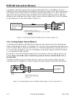
3.4.14 Low-Level Pulse Input Module
A schematic representation of the field wiring connections to the input circuit of the Low-Level Pulse
Input module is shown in Figure 3-20. The field wiring connects through a separate terminal block that
plugs in next to the module allowing replacement of the module without disconnecting field wiring.
NOTE:
The Low-Level Pulse Input module is designed to operate only with pulse-generating
devices having their own power source. The module does not work with non-powered devices.
The Low-Level Pulse Input module operates when a field device provides a pulsed voltage between
30 millivolts and 3 volts peak-to-peak across terminals B and C of the module. The pulsed voltage is
counted and accumulated by the module, which provides the accumulated count to the ROC electronics
on request.
SELF-POWERED
PULSE DEVICE
+
–
+
C
B
–
A
N/C
200K
200K
DOC0150A
PI LL
Figure 3-20. Low-Level Pulse Input Module Field Wiring Schematic
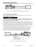
3.4.15 RTD Input Module
The RTD input module monitors the temperature signal from a Resistance Temperature Detector (RTD)
sensor or probe. The RTD module is isolated, reducing the possibility of lightning damage. A Lightning
Protection Module (LPM) will not protect the RTD, but it helps protect the rack in which the module is
installed.
The RTD module must to be calibrated while disconnected from the RTD probe; therefore, it may be
more convenient to perform calibration before connecting the field wiring. However, if the field wiring
between the ROC and the RTD probe is long enough to add a significant resistance, then calibration
should be performed in a manner that takes this into account.
For a three- or four-wire RTD with the wires used to connect up each leg are of the same length and
size, the error generated will be zero or at least no different for any given length. This is because the
RTD input uses the resistance of the wire loop(s) not passing through the RTD to correct for the wire
resistance of the loop with the RTD.
3.4.15.1 Calibrating the RTD Module
The following instructions describe how to calibrate an RTD input channel for use with an RTD probe
having an alpha value of either 0.00385 or 0.00392 ohms/degree C. This procedure requires a resistance
decade box with 0.01-ohm steps and an accuracy of
±
1%. You also need a personal computer running
ROCLINK configuration software.
NOTE:
In ROCLINK configuration software, use the Calibrate button associated with the
Analog Input configuration.


