ROC364 Instruction Manual
2-12
Master Controller Unit, I/O Module Rack, and Wiring
Rev Jun/05
2.5 Troubleshooting and Repair
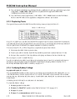
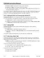
The troubleshooting and repair procedures help identify and replace faulty boards, fuses, and
FlashPACs. Refer to Section 3 for troubleshooting I/O modules or Section 4 for troubleshooting and
replacing a communications card. Return faulty boards and FlashPACs to your local sales representative
for repair or replacement.
The following tools are required for troubleshooting:
♦
IBM-compatible personal computer.
♦
ROCLINK configuration software.
♦
Digital multimeter, Fluke 8060A or equivalent.
2.5.1 LED Indicators
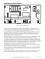
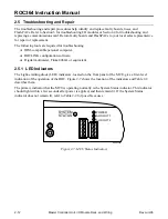
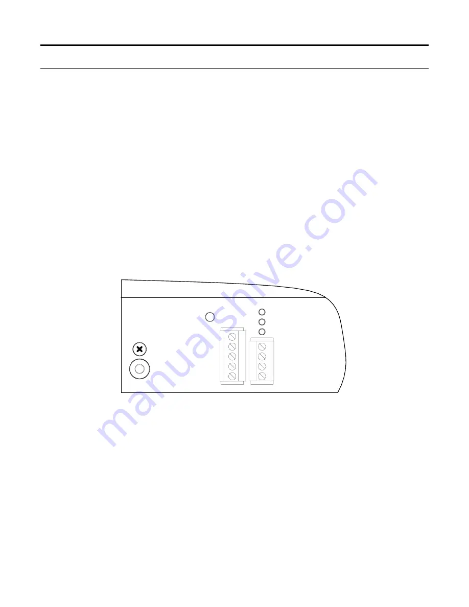
The Light-emitting diode (LED) indicators, located on the front panel of the MCU, give a first-level
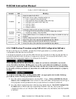
indication of the operation of the ROC. Figure 2-7 shows the location of the indicators and Table 2-2
describes them.
The primary indicator that the MCU is operating normally is the System Status indicator. This indicator
should light within a few seconds after power is applied, and then remain lit. If the System Status
indicator does not remain lit, refer to Table 2-2 for possible causes.
POWER
AUX OUT 1
AUX OUT 2
SYSTEM
STATUS
DOC0122A
Figure 2-7. MCU Status Indicators

