


ROC364 Instruction Manual
3-19
Input and Output Modules
Rev Jun/05
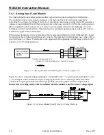
3.4.15.2 Connecting RTD Module Field Wiring
The RTD sensor connects to the RTD module with ordinary copper wire. To avoid a loss in accuracy,
sensor wires should be equal in length, of the same material, and the same gauge. To avoid possible
damage to the RTD module from induced voltages, sensor wires should be kept as short as possible.
This is typically 3.35 meters (100 feet) or less. A schematic representation of the field wiring
connections to the input circuit of the RTD input module displays in Figure 3-22, Figure 3-23, Figure
3-24, and Figure 3-25.
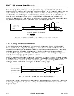
Two-wire RTDs are connected to module terminals A and B. Terminal B must be connected to terminal
C, as shown in Figure 3-22.
I SRC
+
-
2-WIRE, 100 OHM
ROC-POWERED
RTD PROBE
RED
WHT
B
WHT
C
WHT
RED
A
DOC4007A
Modified
RTD
Figure 3-22. RTD Input Module Field Wiring for Two-Wire RTDs
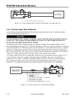
Three-wire RTDs have an active element loop and a compensation loop. The active element loop
connects across terminals A and B. The compensation loop connects across B and C. The compensation
loop helps increase the accuracy of the temperature measurement by allowing the RTD module to
compensate for the resistance of hookup wire used between the probe and RTD module.
In operation, the RTD module subtracts the resistance between terminals B and C from the resistance
between terminals A and B. The remainder is the resistance of only the active element of the probe. This
compensation becomes more important as the resistance of the hookup wire increases with distance
between the probe and the ROC. Of course, in order to perform properly, the compensation loop must
use the same type, size, and length of hookup wire as the active element loop.
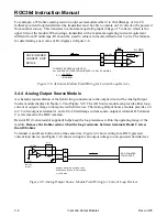
The RTD module is designed for only one compensation loop, and this loop is not isolated from the
active element loop because terminal B is common to both loops. In the 3-wire RTD, the wires connect
to module terminals A, B, and C, as shown in Figure 3-23.
It is important to match the color-coding of the RTD probe wires to the proper module terminal, because
the probe wire colors vary between manufacturers. To determine which leads are for the compensation
loop and which are for the active element, read the resistance across the probe wires with an ohmmeter.
The compensation loop reads 0 ohms, and the RTD element reads a resistance value matching the
temperature curve of the RTD.
3-WIRE,100-OHM,
RTD PROBE
WHT
WHT
RED
WHT
C
RED
WHT
B
A
DOC0161A
Modified
RTD
I SRC
Figure 3-23. RTD Input Module Field Wiring for Three-Wire RTDs


