


ROC364 Instruction Manual
2-11
Master Controller Unit, I/O Module Rack, and Wiring
Rev Jun/05
The switches employed in the auxiliary outputs are solid-state relays and exhibit a voltage drop
proportional to the current load, typically in the range of 0 to 2 volts dc. The relays can be controlled
automatically using an FST that has been set up to determine the switching conditions. If a FlashPAC is
installed, the auxiliary outputs are switched by using the Status parameter of Discrete Output Point
Number E3 or E4. An LED indicator for each output is activated when the respective output is
energized.
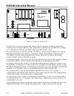
The AUX PWR OUT 1 and AUX PWR OUT 2 terminals are fused at 5 amps by fuses F2 and F3, which
are accessible on the front panel. Refer to Section 2.5.3, Replacing Fuses, on page 2-14.
2.4.4 Connecting Communications Wiring
The ROC has the flexibility to communicate to external devices using several different formats and
protocols. Connectors located on the front panel of the ROC provide both Operator Interface
and data communications.
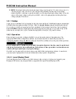
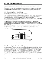
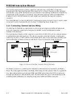
The Local Operator Interface (LOI) connector is a serial EIA-232 (RS-232) port for communications to
a configuration and monitoring device. This device is typically a personal computer. A null modem
cable (wires to pins 2, 3, and 5, with the wires between pins 2 and 3 cross-connected) is normally used
between the Operator Interface connector and the PC. Figure 2-6 shows the wiring for this port.
Figure 2-6. Operator Interface Connector Wiring Schematic
The Display connector is a parallel port for dedicated communications to an optional Local Display
Panel. The cable supplied with the Local Display Panel plugs into this connector. Refer to Appendix B.
Two data communications ports, labeled COM1 and COM2 on the front of the MCU, are activated
through optional plug-in communications cards. Section 4 details the types of communications cards
available and has information on connecting wiring to the COM1 and COM2 connectors.


