ROC364 Instruction Manual
2-19
Master Controller Unit, I/O Module Rack, and Wiring
Rev Jun/05
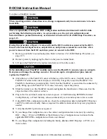
2.5.12 Removing and Replacing the MCU Assembly
Remove and replace the MCU assembly as instructed in the following procedure.
When repairing units in a hazardous area, change components only in an area known to be non-
hazardous.
There is a possibility of losing the ROC configuration and historical data held in RAM while
performing the following procedure. As a precaution, save the current configuration and
historical data to permanent memory as instructed in Section 2.5.2, RAM Backup Procedure, on
page 2-13.
During this procedure, all power is removed from the ROC and devices powered by the ROC.
Ensure all connected input devices, output devices, and processes remain in a safe state when
power is removed from the ROC and when power is restored to the ROC.
1.
Unplug the power connector from the ROC.
2.
Unplug all connectors and terminal blocks from the MCU.
3.
Loosen the screws that secure the MCU case to the ROC backplate.
4.
Move the MCU up to disengage it from the I/O module rack and to slide two keyhole slots in the
case backplate into position to fit over the heads of concealed alignment screws. Then lift the
MCU away from the ROC backplate.
5.
If you are reasonably sure the FlashPAC modules are functioning (keep in mind all RAM is
normally cleared during factory servicing), you can remove them by unscrewing the two
thumbscrews of their retainer and gently pulling each one from its socket.
6.
The MCU must be returned as an assembly (the MCU board must remain in the metal case) to
your local sales representative for repair. If the ROC is equipped with one or two
communications cards, the cards can be removed if desired before returning the MCU assembly.
Follow the applicable procedure in Section 4 for removing these cards.
7.
To install a new or repaired MCU assembly, reverse the procedure used for removal in the
previous steps.
8.
Reconnect power to the ROC by plugging in the power terminal block.
9.
Using ROCLINK configuration software, check the configuration data including ROC Displays
and FSTs, and load or modify them as required. In addition, load and start any user programs as
needed.
10.
Verify that the ROC performs as required.
11.
If you changed the configuration, save the current configuration data to memory by selecting
ROC > Flags > Write to EEPROM or Flash Memory Save Configuration as instructed in the
applicable ROCLINK configuration software user manual. Also, if you changed the
configuration including the history database, ROC Displays, or FSTs, save them to disk.

