ROC364 Instruction Manual
I-6 Index
Rev
Jun/05
SHUTDOWN .................................................... 4-16, 4-17
SIGN.............................................................................B-5
Site Requirements......................................................... 1-4
Slow Pulse Inputs
Isolated..................................................................... 3-4
Isolated Troubleshooting........................................ 3-26
Isolated Wiring....................................................... 3-16
Source ...................................................................... 3-4
Source Troubleshooting ......................................... 3-26
Source Wiring ........................................................ 3-15
Solar
Panels....................................................................... 1-4
Specifications
Communication Card ............................................. 4-21
I/O Converter Card .................................................. 5-4
I/O Modules ........................................................... 3-30
Lightning Protection Module .................................. A-3
Local Display Panel ...............................................B-23
ROC364 ................................................................. 2-20
Startup................................................................ 1-10, 1-11
Voltage Requirements .............................................. 2-8
Surge Protection Device ............................................... 1-6
Switch
Switch Input to DI Isolated Module.........................C-5
Switch Input to DI Source Module ..........................C-5
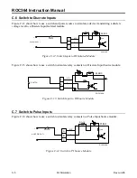
Switch to Discrete Inputs .........................................C-5
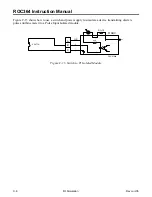
Switch to PI Isolated Module...................................C-6
Switch to PI Source Module ....................................C-5
Switch to Pulse Inputs..............................................C-5
SYS...............................................................................B-6
SYS Parameter Displays.............................................B-12
Display 1 ................................................................B-12
Display 2 ................................................................B-12
Display 3 ................................................................B-13
Display 4 ................................................................B-13
System Status..................................................... 2-12, 2-13
T
Table 1-1. Power Consumption of the ROC364 and
Powered Devices......................................................... 1-8
Table 1-2. Power Consumption of the I/O Modules .... 1-9
Table 2-1. ROC Memory Map .................................... 2-4
Table 2-2. MCU LED Indicators ............................... 2-13
Table 2-3. ROC Fuses................................................ 2-14
Table 3-1. Calibration Resistance Values................... 3-18
Table 3-2. Analog Input Module Typical Configuration
Values........................................................................ 3-22
Table 4-1. Communications Card LED Indicators....... 4-3
Table 4-2. Jumper Positions for the Modem Cards.... 4-10
Table 4-3. Radio and Leased-Line Modem
Communications Card Attenuation Levels ............... 4-11
Table 4-4. ROC300-Series Communications Card Signals
.................................................................................. 4-12
Table 5-1. I/O Converter Card Requirements ............... 5-2
Table B-1. Function Key Labels and Descriptions ......B-5
Table B-2. Main Menu Items of the Local Display Panel
....................................................................................B-6
Table B-3. I/O Menu Point Types ................................B-7
Table B-4. Discrete Input Point Display Parameters ...B-7
Table B-5. Discrete Output Point Display Parameters
....................................................................................B-8
Table B-6. Analog Input Point Display Parameters .....B-9
Table B-7. Analog Output Point Display Parameters
..................................................................................B-10
Table B-8. Pulse Input Point Display Parameters ...... B-11
Table B-9. SYS Parameter Display 1.........................B-12
Table B-10. SYS Parameter Display 2.......................B-12
Table B-11. SYS Parameter Display 3.......................B-13
Table B-12. SYS Parameter Display 4.......................B-13
Table B-13. DB Point Display Parameters ................B-14
Table B-14. AGA Point Display 1 Parameters...........B-15
Table B-15. AGA Point Display 2 Parameters...........B-16
Table B-16. AGA Point Display 3 Parameters...........B-16
Table B-17. PID Point Display Parameters................B-19
Table B-18. FST Point Display Parameters ...............B-19
Table B-19. MSG Point Display Parameters .............B-20
Table B-20. LCD Menu Display Parameters – View
..................................................................................B-21
Temperature of ROC.......................................................2-4
Totaling Power Requirements..................................... 1-10
Troubleshooting.......................................................... 2-12
Analog Inputs ........................................................ 3-22
Analog Outputs...................................................... 3-22
Communications Cards.......................................... 4-19
Discrete Input Isolated ........................................... 3-24
Discrete Input Source ............................................ 3-24
Discrete Output Isolated ........................................ 3-24
Discrete Output Relay............................................ 3-25
Discrete Output Source.......................................... 3-24
HART Interface Module ........................................ 3-27
I/O Converter Card .................................................. 5-3
I/O Modules ........................................................... 3-21
I/O Simulation .........................................................C-1
Lightning Protection Module...................................A-2
Low-Level Pulse Input........................................... 3-26
Performing a Cold Start ......................................... 2-16
Performing a Reset ................................................ 2-16
Pulse Inputs............................................................ 3-25
Removing and Replacing the MCU Assembly ...... 2-19
Replacing a FlashPAC ........................................... 2-16
Replacing the Battery ............................................ 2-18
Resetting the Local Display Panel .........................B-22
RTD Input .............................................................. 3-27
Slow Pulse Input Isolated ...................................... 3-26
Verifying Battery Voltage ...................................... 2-14
Verifying RAM ...................................................... 2-15
Verifying the ROC can Communicate with the PC
......................................................................... 2-15
Turbine Meter ...............................................................C-6
TXD.............................................................................. 4-3
U
UP.................................................................................B-5
User Manuals................................................................ 1-1


