ROC364 Instruction Manual
3-12
Input and Output Modules
Rev Jun/05
When using the Discrete Output Source module to drive an inductive load, such as a relay coil, a
suppression diode should be placed across the input terminals to the load. This protects the
module from the reverse Electro-Motive Force (EMF) spike generated when the inductive load is
switched off.
1 Amp
DOC0145A
+5V
DO SRC
V
S
CONTROL
I LIMIT
B
–
C
–
N/C
+
A
+
DISCRETE DEVICE
ROC-POWERED
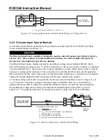
Figure 3-13. Discrete Output Source Module Field Wiring
3.4.8 Discrete Output Isolated Module
A schematic representation of the field wiring connections to the output circuit of the Discrete Output
Isolated module is shown in Figure 3-14.
NOTE:
The Discrete Output Isolated module is designed to operate only with discrete devices
having their own power source. The module is inoperative with non-powered devices.
The Discrete Output Isolated module operates by providing a low or high-output resistance to a field
device. When the field device provides a voltage across terminals A and B of the module, current either
flows or is switched off by the DO Isolated module. The switching is controlled by the ROC electronics.
1 Amp
DOC0146A
(Modified)
CONTROL
DO ISO
+5V
B
TERMINAL A CONNECTION IS COMMON
TERMINAL B CONNECTION TO BE MADE FOR NORMALLY OPEN APPLICATIONS
TERMINAL C CONNECTION IS NO CONNECT
V
O
= VOLTAGE FROM DISCRETE DEVICE = 11 TO 30 VDC, 1.0 A MAX
N/C
C
–
A
DISCRETE DEVICE
SELF-POWERED
V
O
+
COM
NO
Figure 3-14. Discrete Output Isolated Module Field Wiring

