


ROC364 Instruction Manual
2-14
Master Controller Unit, I/O Module Rack, and Wiring
Rev Jun/05
3.
Save all historical database logs (Minute, Hourly, and Daily), Event Log, and Alarm Log to disk
using ROC >
Collect Data “All”
function as explained in the applicable ROCLINK
configuration software user manual.
4.
Save the FSTs to disk using Utilities > FST Editor > FST >
Write
function in the FST Editor.
Refer to the FST Editor in the applicable configuration software user manual.
2.5.3 Replacing Fuses
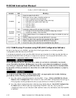
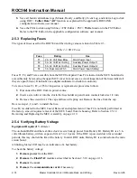
The types of fuses used for the ROC364 and their rating values are listed in Table 2-3.
Table 2-3. ROC Fuses
Fuse Rating
Use
F1
2 A, 32 Volt Slow Blow
Main Power Input
F2
5 A, 32 Volt Fast Acting
Auxiliary Power Output 1
F3
5 A, 32 Volt Fast Acting
Auxiliary Power Output 2
F4
3 A, Bussman GFA 3
Main Power Input (Safety)
Fuses F1, F2, and F3 are accessible from the MCU front panel. Fuse F4 is located on the MCU board and is
accessible only by removing the upper MCU cover. In most cases, a visual inspection of the fuses indicate if
they are open (blown). If in doubt, use a digital multimeter to check for continuity.
To remove fuses F1, F2, or F3 for inspection or replacement, proceed as follows:
1.
Disconnect the ROC from its power source.
2.
Insert a screwdriver into the slot in the fuse holder cap and rotate counterclockwise 1/4 turn.
3.
Remove the screwdriver. The cap and fuse will spring out. Remove the fuse from the cap.
Reverse steps 1, 2, and 3 to install the fuse.
Fuse F4 is soldered to the MCU board. Removal and replacement of fuse F4 is normally performed at
the factory, since it requires removal of the MCU board from its housing. Refer to Section 2.5.12,
Removing and Replacing the MCU Assembly, on page 2-19.
2.5.4 Verifying Battery Voltage
Equipment Required:
Voltmeter
The on-board RAM and the real-time clock receive backup power from Battery B1. Battery B1 is a 3.6-
volts lithium battery, with an expected life of 5 to 10 years. If the ROC is powered down for extended
periods, this may shorten the life of the battery. In older ROC units, Battery B1 is soldered onto the main
circuit board.
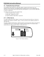
A blinking Status LED may be an indication of a bad battery.
To check the battery voltage:
1.
Remove
power
from the ROC.
2.
Remove
the
FlashPAC
module as described in Section 2.5.10 on page 2-16.
3.
Remove
the
cover
.
4.
Remove
the
communications cards
if necessary.


