Chapter 7 Application Guidance 41
EV3200 Door Control Inverter User Manual
L
N
50/60Hz
M
A
B
CD
U
V
W
PE
PB3
PC3
PA3
MCCB
COM
OD
PG
COM
P24
PC1
PA1
PC2
PA2
X1
X2
Single phase
power supply
EV3200 inverter
E
lev
at
or
do
or
me
chan
ic
al
s
yste
m
Cont
ro
l syste
m
C
ontr
ol sys
te
m
OD command input
CD command input
Light curtain NO input
Safety edge NO input
PG: pulse generator
Fault relay
Complete OD
relay output
Complete CD
relay output
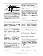
Figure 7-3 System wiring diagram for distance control 1(asynchronous motor)
L
N
50/60Hz
M
X1
CD
U
V
W
PE
PB3
PC3
PA3
MCCB
COM
OD
PG
PC1
PA1
PC2
X2
PA2
SK2
1
5
6
10
11
15
Single phase
power supply
EV3200 inverter
El
ev
ato
r doo
r
m
echa
nic
al
system
C
ontr
ol sys
te
m
OD command input
CD command input
Light curtain NO input
Safety edge NO input
C
ontr
ol sys
te
m
PG: pulse generator
Fault relay
Complete OD
relay output
Complete CD
relay output
Figure 7-4 System wiring diagram for distance control 1(synchronous motor, UVW incremental PG)
7.3.2 Testing Procedures
1. Do the wiring according to Figure 7-3 and Figure 7-4 (refer to
3.4 PG Terminals Of Synchronous Motor
and
3.5 Wiring
Diagram Of Inverter
for PG wiring).
2. Switch on the inverter, set F9.18 to 2 to restore the factory settings.
3. Carry out motor tuning according to instructions provided in
7.1 Motor Type Setup
. The parameters will be saved
automatically after tuning.
4. Set F0.01 to 1, set F4.01 and F4.02 (0: forward, 1: reverse) correctly. After exiting the programming status, press
(or
)
to start the operation in keypad control mode, and adjust F4.02 setting according to the actual operating conditions. If over
current or over load occurs, or the output current exceeds the motor rated current, adjust the setting of F4.02 to ensure correct
PG parameter settings, and restart the inverter.
5. Switch off the inverter, connect the elevator door mechanical system and switch on the inverter again.
6) Set F0.02 to 1 (keypad control mode), select auto-learning speed properly via F4.04, set F4.05 to 1, press
to start
door-width auto learning, and the motor operates according to the procedures of CD
→
OD
→
CD. The inverter stops after the
last motor catching. The door width information will be saved automatically after auto-learning.


