Chapter 6 Parameter Description 29
EV3200 Door Control Inverter User Manual
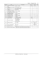
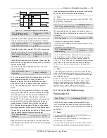
OD obstruction
signal
OD signal
Running frequency
(positive for OD,
negative for CD)
10s
<10s
Time
CD signal
Time
Time
Time
Figure 6-12 Time sequence diagram for OD obstruction
F3.11 Maintaining time for
complete OD in demo mode
Setting range: 1 ~ 3600s
【
2.0
】
Defines the interval from complete OD to CD in demo mode.
It can be set according to the actual requirement of demo.
F3.12 Maintaining time for
complete CD in demo mode
Setting range: 1 ~ 3600s
【
2.0
】
Defines the interval from complete CD to OD in demo mode.
It can be set according to the actual requirement of demo.
F3.13 Preset CD/OD times in
demo mode
Setting range: 0 ~ 9999
【
0
】
Defines the operation times in demo mode. When the actual
operation times is bigger than the setting of F3.13, the demo
is ended automatically.
If F3.13=0, this function is disabled and demo will not be
ended automatically.
F3.14 CD/OD times record in
demo mode
Range: 0 ~ 9999
【
0
】
F3.14 is the recorded CD and OD times in demo mode. The
value is saved upon power off. When the inverter is
powered on the next time, the operation times in demo
mode will be counted and added to the previous value of
F3.14. One is added every time the door is opened or
closed.
Demo mode is a cyclic operation of OD and CD. Pressing
the
key starts the demo. The door is opened according
to the operation curve. The inverter starts timing after the
door is opened completely. When the time reaches the
setting of F3.11, the inverter starts reverse running, and the
door is closed. The inverter starts timing after the door is
closed completely. When the time reaches the setting of
F3.12, the door is opened again. The door is thus opened
and closed repeatedly. Pressing the
key ends the demo.
Demo can be under both speed control and distance control.
It can be used for demonstration and burning test.
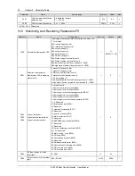
F3.15 Auto restet times
upon fault
Setting range: 0 ~ 100
【
0
】
When fault occurs while the inverter is running, the inverter
stops its output. Two seconds later, it will reset automatically
and continue to run.
Setting this parameter disables the automatic reset function,
and the inverter can only be reset by manually.
Note
The inverter will not reset automatically when E024, E025, E028,
E029, E030, E031 faults occur.
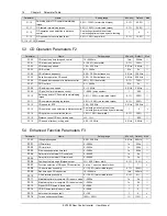
F3.16 Torque enhance coefficient
Setting range: 100% ~
350%
【
115%
】
This parameter is used to enhance the switching torque in
first time operation or self-learning process, so as to prevent
error action.
F3.17 Fan control
Setting range: 0 ~ 2
【
0
】
0: fan does not start during inverter operation
1: fan starts when heatsink temperature is higher than 65°C during
inverter operation
2: fan starts during inverter operation
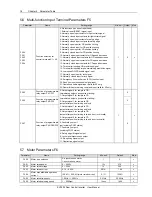
F3.18 Percentage or pulse
number selection
Setting range: 0 ~ 1
【
0
】
0: F1.01, F1.06, F1.13, F2.01, F2.06 and F2.14 are percentages.
1: F1.01, F1.06, F1.13, F2.01, F2.06 and F2.14 are numbers.
After confirming the setting of F3.18 as 0, function codes F1.01,
F1.06, F1.13, F2.01, F2.06 and F2.14 are based on the percentage
of door width. On the other hand, after confirming the setting of
F3.18 as 1, such function codes are based on the actual pulse
number.
Note
1. After changing F3.18 from 0 to 1, and after getting the door
width or the door width total pulse number, function codes F1.01,
F1.06, F1.13, F2.01, F2.06 and F2.14 must be reset based on the
door width pulse number.
2. When F3.18 is set to 1, the setting ranges of F1.01, F1.06,
F1.13, F2.01, F2.06 and F2.14 are 0 ~ 32767. If the set pulse
number is bigger than 9999, only the higher 4 digits will be
displayed, while the decimal point after the forth digit will be
lighted to indicate that the fifth digit is not displayed.
6.5 Door Width Self-learning
Parameters F4
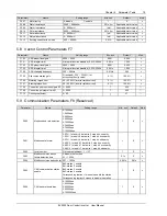
F4.00 PG type
Setting range: 0, 1
【
0
】
Set F4.00 correctly according to the selected PG type.
If 24V incremental PG (open-collector or push-pull type) is
selected, set F4.00 to 0. If UVW incremental PG is selected,
set F4.00 to 1.
Note
1. For inverters EV3200-2S0002A and EV3200-2S0004A, the
default setting of this parameter is 0.
2. For inverters EV3200-2S0002S and EV3200-2S0004S, the
default setting of this parameter is 1.
3. Function code F4.00 changes automatically with the change of
F6.00. The value of F4.00 is always kept the same as F6.00.


