


Chapter 6 Parameter Description 31
EV3200 Door Control Inverter User Manual
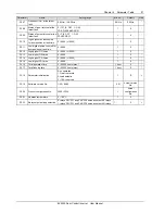
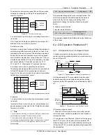
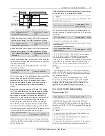
Pulley
Traction wheel
N1
Motor shaft
N2
Figure 6-13 Illustration of ratio of gear
F4.11 Asynchronous
single/dual motor selection
Setting range: 0 ~ 1
【
0
】
0: single motor control (asynchronous or synchronous).
1: dual motors control (asynchronous).
When F4.11 is set 0, the inverter works in the single motor
control mode, which is the only mode for synchronous
motors. When F4.11 is set 1, the inverter works in dual
asynchronous motors control mode, the inverter then can
two asynchronous motors whose parameters are set the
same. However, the motor tuning operation requires the
single motor control mode (F4.11 = 0), or the system will
report E028.
6.6 Multi-function Input Terminal
Parameters F5
Functions and parameters of control terminals X1 ~ X5 are
defined by the following parameters.
F5.00 Function selection for
control terminal X1
Setting range: 0 ~ 20
【
0
】
F5.01 Function selection for
control terminal X2
Setting range: 0 ~ 20
【
0
】
F5.02 Function selection for
control terminal X3
Setting range: 0 ~ 20
【
0
】
F5.03 Function selection for
control terminal X4
Setting range: 0 ~ 20
【
0
】
F5.04 Function selection for
control terminal X5
Setting range: 0 ~ 22
【
0
】
Control terminals X1 ~ X5 are programmable input terminals,
and their functions can be defined by F5.00 ~ F5.04. The
functions are listed in Table 6-1.
Table 6-1 Function selection for multi-function inputs
Settings
Functions
Settings
Functions
0 No
functions
12
Normally open input
contacts for CD
speed decrease
1
External reset (RESET)
signal input
13
Normally closd input
contacts for CD
speed decrease
2
Normally open input
contacts for light curtain
signal
14
Terminal for inputting
OD prohibition signal
3
Normally closed input
contacts for light curtain
signal
15
Terminal for
disabling torque
maintaining
Settings
Functions
Settings
Functions
4
Normally open input
contacts for safety edge
16
Low speed OD/CD
enable signal input
5
Normally closed input
contacts for safety edge
17
Normally open input
for lock signal
6
Normally open input for
OD position limiting
18
Normally closed
input for lock signal
7
Normally closed input for
OD position limiting
19
EFS function input
8
Normally open input for
CD position limiting
20
Rush hour operation
enable signal input
9
Normally closed input for
CD position limiting
21
Operation enable
signal input (valid for
X5 only)
10
Normally open input
contacts for OD speed
decrease
22
Door width
auto-learning
command input
(valid for X5 only)
11
Normally closed input
contacts for OD speed
decrease
Note
When setting parameters from F5.00 to F5.04, only 0 (no function)
can be set repetitively, other settings (1 ~ 22) can not.
0: No function
1: External reset (RESET) signal input
When a fault occurs, the inverter can be reset via this
terminal. This function is enabled at the falling edge of the
pulse, and its function is the same with that of the
key
on the keypad.
2, 3: Normally open/closed input contacts for light curtain
signal
In CD process, if this terminal is activated, CD obstruction
protection will be executed. During the re-opening process,
the inverter will not response to CD command.
If the door has reached the CD position limit, this protection
signal is ineffective.
4, 5: Normally open/closed input contacts for safety edge
In CD process, if this terminal is activated, CD obstruction
protection will be executed. During the re-opening process,
the inverter will not response to CD command.
If the door has reached the CD position limit, this protection
signal is ineffective.
6, 7: Normally open/closed input for OD position limiting
In OD process under speed control, the inverter will take
actions of OD position limiting after this signal is enabled.
8, 9: Normally open/closed input for CD position limiting
In CD process under speed control, the inverter will take
actions of CD position limiting after this signal is enabled.
10, 11: Normally open/closed input for OD speed decrease
In OD process under speed control, the inverter starts low
speed operation in ending phase after the normally
open/closed input for OD speed decrease is enabled.