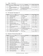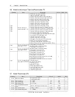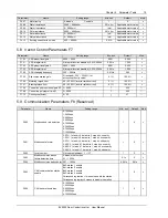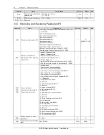
Chapter 6 Parameter Description 23
EV3200 Door Control Inverter User Manual
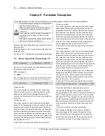
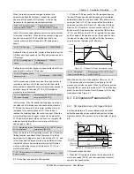
The elevator control system sends OD and CD commands
to realize door opening or closing. The operating logic is
shown in Figure 6-1.
0
K
1
K
2
0
1
0
0
1
1
1
Running
command
OD
CD
Stop
K1
K2
OD
COM
CD
EV3200
inverter
.
.
.
OD
Figure 6-1 Terminal control logic
3: communication control mode for controlling elevator door
(reserved)
OD, CD and auto-learning are performed according to the
definition of the control word in protocol.
4: auto-demo mode
Auto-demo mode is used for demonstrating the operation or
commissioning of the inverter in the factory, no need to be
controlled by the control system. The auto-demo mode can
be set after the inverter's operation curve is set in keypad
control mode for elevator door control. Press the
key to
start the demonstration of OD and CD repetitively, the times
and interval between CD and OD can be set by F3.11,
F3.12 and F3.13. Pressing the
key stops the demo.
5: terminal control mode of general-purpose inverter
The starting and stopping of the motor can be controlled via
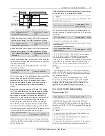
OD and CD terminals. The operation logic is shown in
Figure 6-2. In this control mode, the inverter will not perform
the functions of elevator door control.
0
K
1
K
2
0
1
0
0
1
1
1
Running
command
FWD
REV
Stop
K1
K2
OD
COM
CD
EV3200
inverter
.
.
.
FWD
Figure 6-2 Terminal control mode of general-purpose inverter
6: reserved
7: communication control mode of general-purpose inverter
(reserved)
Irrelevant to the door control logic, the running frequency in
general-purpose inverter mode is the OD high speed phase
frequency by default.
Note
1. Door width auto-learning is valid only in keypad control mode
and terminal control mode for elevator door control.
2. In keypad control mode, pressing the
key starts
auto-learning. In terminal control mode for elevator door control,
you need to set F5.04 to 22, and input the valid level to start
auto-learning.
F0.03 Running direction selection
Setting range: 0, 1
【
0
】
This parameter changes the motor running direction. The
motor running direction is determined after the motor is
wired correctly. You can change the setting of this
parameter to change the direction without rewiring the
motor.
0: same as preset direction
1: reverse to preset direction
F0.04 Max. output frequency
Setting range: 50.00 ~
128.00Hz
【
50.00
】
The parameter defines the allowable max output frequency
of the inverter.
6.2 OD Operation Parameters F1
6.2.1 OD Operation Curve For Speed Control
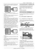
In speed control mode, the locations of various control
contacts (operating switches mounted on elevator door) are
shown in Figure 6-3.
CD
OD speed
decrease contacts
OD position
limiting signal
OD
Position of complete OD
CD speed
CD position
limiting signal
Position of complete CD
decrease contacts
Figure 6-3 Speed decrease contacts for speed control
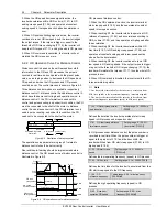
Set the parameters in F1 group related to speed control,
define the speed decrease contacts and position limiting
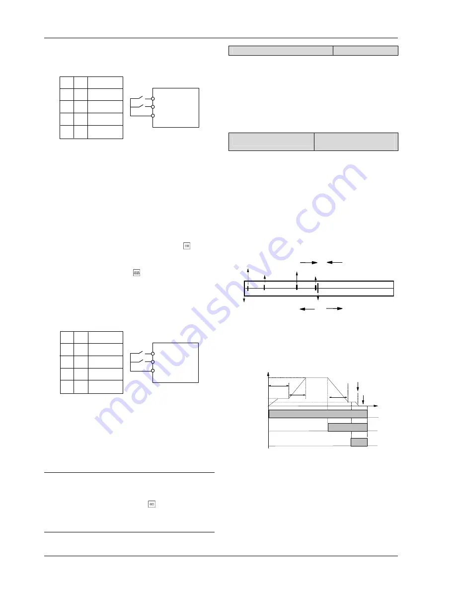
signal accurately. OD operation curve is illustrated in Figure
6-4.
Frequency
F1.04
Time
F1.02
F1.08
F1.00
F1.11
F1.10
F1.03
OD
OD speed
decrease signal
OD position
limiting signal
ON
OFF
ON
OFF
ON
OFF
F1.07
Figure 6-4 OD operation curve for speed control
OD process of speed control:
1. When the OD command is active, the inverter starts at
start creep speed, and then operates at constant speed in
low-speed section.
2. Timing begins when OD starts. When the OD start creep
time (F1.00) is over, the inverter starts to operate at OD
reference frequency (F1.04), and accelerates according to
OD Acc time (F1.03), and then operates at high speed after
the acceleration.


