Chapter 3 Electrical Installation 9
EV3200 Door Control Inverter User Manual
3.4 PG Terminals Of Synchronous Motor
The motor of inverters EV3200-2S0002S and EV3200-2S0004S is three-phase AC synchronous motor. It can use the UWV
incremental PG. For the UWV incremental PG, the PG signal is connected to terminal SK2. The pin assignment of terminal
SK2 is shown in Figure 3-5.
1
5
6
10
11
15
Figure 3-5 Pin assignment of terminal SK2
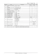
Table 3-6 Description of terminal SK2
Pin No.
Signal description
Pin No.
Signal description
Pin No.
Signal description
1 U- 6 U+ 11 /
2 V- 7 V+ 12
+5V
3 A- 8 A+ 13
GND
4 B- 9 B+ 14 Z-
5 W- 10 W+ 15 Z+
3.5 Wiring Diagram Of Inverter
The basic wiring between the inverter's input, output terminals and external equipment is illustrated in Figure 3-6.
In the figure, the control terminals are used to control the inverter operation, and output the inverter status data to external
monitoring equipment. The wiring method depends on your application.
L
N
L
N
Single phase
power supply
50/60Hz
M
A
B
X
1
CD
Incremental
PG signal input 1
Multi-function input terminal 1
P24
U
V
W
PE
Auxiliary
supply
MCCB
Defined as fault relay by default:
Normal: PA3-PB3 closed
Fault: PA3-PC3 closed
COM
OD
OD command input
PB3
PC3
PA3
PC1
PA1
PC2
PG power supply
PA2
1
5
6
10
11
15
SK2
(
configured only for EV3200-2S0002S
and EV3200-2S0004S
)
X
2
X
3
X
4
X
5
PG signal input 2
Multi-function input terminal 2
Multi-function input terminal 3
Multi-function input terminal 4
Multi-function input terminal 5
CD command input
Synchronous motor UVW PG signal input
Defined as complete OD relay by default:
Incomplete: PA1-PC1 closed
Complete: PA1-PC1 open
Defined as complete CD relay by default:
Incomplete: PA2-PC2 closed
Complete: PA2-PC2 open
Incremental
Figure 3-6 Basic wiring diagram
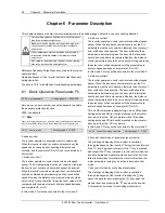
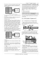
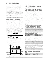
The 24V incremental PG of EV3200 door control inverter can input the following two kinds of PG signals. The PG working
power supply should be 24V.


