Chapter 6 Parameter Description 35
EV3200 Door Control Inverter User Manual
Note
Normally, there is no need to change the PI parameters of current
loop. Do not change them unless absolutely necessary.
F7.10 Filtering coefficient
Setbting range: 0 ~ 63
【
27
】
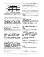
This parameter is the filtering coefficient for high speed and
low speed feedback, as shown in Figure 6-19.
0
1
2
3
4
5
Low speed
filtering times
Bit
High speed
filtering times
Figure 6-19 Filtering coefficient
Each filtering parameter accounts for 3 bits. The decimal
number converted from the 3-bit number is the filtering
times of the filtering parameter.
For example, high speed filtering needs 3 times, the
corresponding binary number is 011B, therefore the
corresponding Bit 5, Bit 4, and Bit 3 are respectively 0, 1
and 1; low speed filtering needs 1 time, the corresponding
Bit 2, Bit 1 and Bit 0 are respectively 0, 0 and 1; so the 6-bit
binary number is 011001B, which, if converted to a decimal
number, is 25, thus 25 is the setting of F2.13.
Note
Normally, the filtering coefficient does not need adjustment, but in
applications subject to bit interference, the filtering times can be
increased.
6.9 Communication Parameters F8
(Reserved)
EV3200 inverter provides reserved standard RS485 and
CAN communication ports, which use open Modbus serial
communication protocol.
If you wish to control EV3200 inverter through
communication, you may connect it to a computer or an
PLC, or you may control it through a communication
adapter.
F8.00 Modbus baud rate selection
Setting range: 0 ~ 7
【
4
】
Defines the serial communication speed rate.
0: 1200bps
1: 2400bps
2: 4800bps
3: 9600bps
4: 19200bps
5: 38400bps
6: 115200bps
7: 125000bps
F8.01 Modbus data format
Setting range: 0 ~ 5
【
0
】
Defines the data format adopted in serial communication
protocol.
0: RTU, 1 start bit, 8 data bits, 2 stop bits, no parity
1: RTU, 1 start bit, 8 data bits, 1 stop bit, even parity
2: RTU, 1 start bit, 8 data bits, 1 stop bit, odd parity
3: ASCII, 1 start bit, 7 data bits, 2 stop bits, no parity
4: ASCII, 1 start bit, 7 data bits, 1 stop bit, even parity
5: ASCII, 1 start bit, 7 data bits, 1 stop bit, odd parity
F8.02 Local Number
Setting range: 0 ~ 127
【
5
】
Defines the address of the local inverter in the case a host
controls multiple inverters. The address of each inverter
shall not repeat.
0 is defined as the broadcast address.
F8.03 Modbus communication
failure detection time
Setting range: 0, 0.1 ~ 100.0s
【
0
】
If communication control mode is not selected (F0.02=0 ~ 2
or F0.02=4 ~ 5), this function is disabled.
When F8.03=0, this function is disabled.
When F8.03 is not set to 0, if the communication interrupt
lasts longer than the setting of F8.03, fault code E017
(communication error) will be displayed, and the inverter will
stop.
F8.04 Modbus communication
delay
Setting range: 0.01 ~ 1.000s
【
0.01
】
You may define the response delay of the inverter in
communication according to the speed of the Modbus main
station.
In RTU mode, the actual communication delay shall not be
less than 3.5 character spaces. In ASCII mode, the actual
communication delay shall not be less than 1ms.
F8.05 CAN communication
station enable
Setting range: 0 ~ 15
【
0
】
This parameter is used to select to enable or disable the
communication stations.
Bit 0: station 1 enable
Bit 1: station 2 enable
Bit 2: station 3 enable
Bit 3: station 4 enable
Corresponding station =1 means to enable the station
Corresponding station=0 means to disable the station.
F8.06 CAN baud rate selection
Setting range: 0 ~ 4
【
0
】

