40 Chapter 7 Application Guidance
EV3200 Door Control Inverter User Manual
Note
If the actual operation is reverse to OD/CD command, please change the setting of F0.03 or change the phase connection of motor.
5. After testing, set F0.02 to 2 (terminal control mode), and the inverter will begin to work normally.
7.2.3 Parameter Settings
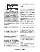
Figure 7-2 provides the parameter settings.
Table 7-2 Parameter settings for speed control
Function code
Name
Setting
Remark
F0.01
Control mode
0
Speed control
F5.00
Function selection for control terminal X1
10
Normally open input contacts for OD speed decrease
F5.01
Function selection for control terminal X2
12
Normally open input contacts for CD speed decrease
F5.02
Function selection for control terminal X3
6
Normally open input for OD position limiting
F5.03
Function selection for control terminal X4
8
Normally open input for CD position limiting
F5.04
Function selection for control terminal X5
2/4
Normally open input contacts for light curtain signal/ safety
edge
F5.05
Function of programmable relay output PA1/PC1
2
Output signal 1 for complete OD
F5.06
Function of programmable relay output PA2/PC2
3
Output signal 1 for complete CD
F1.00
OD start creep time for speed control
500ms
F1.02
OD start creep speed
7Hz
F1.03
OD Acc time
0.5s
F1.04
OD reference frequency
20Hz
F1.05
Rush hour operation OD speed
25Hz
F1.07
OD Dec time
0.5s
F1.08
OD ending creep speed
3Hz
F1.10
Threshold for OD torque changing
50.0%
F1.11
Maintaining torque at OD completion
50.0%
Parameters in this table are factory settings, adjust the OD
parameters according to the actual OD operating
conditions
F2.00
CD start creep time for speed control
500ms
F2.02
CD start creep speed
6Hz
F2.03
CD Acc time
0.5s
F2.04
CD reference frequency
15Hz
F2.05
Rush hour operation CD speed
20Hz
F2.07
CD Dec time
0.5s
F2.08
CD ending creep speed
2Hz
F2.10
Threshold for CD torque changing
50.0%
F2.11
Maintaining torque at CD completion
50.0%
F2.12
CD high speed for EFS
10Hz
Parameters in this table are factory settings, adjust the CD
parameters according to the actual CD operating
conditions
F3.08
CD obstruction sensitivity
100.0%
F3.09
Dec time upon abnormality
300ms
F3.10
OD obstruction sensitivity
100.0%
Parameters in this table are factory settings, adjust the
parameters according to the actual conditions
Note
1. Setting of F3.01 (OD time limit) must be bigger than the sum of time in all phases of OD curve.
2. Setting of F3.02 (CD time limit) must be bigger than the sum of time in all phases of CD curve.
7.3 Distance Control 1
7.3.1 System Wiring Diagram
For distance control 1, PG should be installed on the motor shaft. In distance control, the speed decrease and complete CD
and OD judgments are made according to the actual number of pulses counted. System wiring diagram for distance control is
shown in Figure 7-3 and Figure 7-4.


