127
LTP-8X# switch
LTP-8X(switch)# configure
LTP-8X(switch)(config)# vlan 200,201,98,9
LTP-8X(switch)(config-vlan-range)# tagged front-port 0
LTP-8X(switch)(config-vlan-range)# tagged pon-port 0 – 7
LTP-8X(switch)(config-vlan-range)# exit
LTP-8X(switch)(config)# commit
LTP-8X(switch)(config)# exit
Step 16.
Configure IGMP Proxy for VLAN 98 in the switch view, enable IGMP Proxy and IGMP
Snooping globally, and set the range of allowed IGMP groups.
LTP-8X# switch
LTP-8X(switch)# configure
LTP-8X(switch)(config)# vlan 98
LTP-8X(switch)(config-vlan-range)# ip igmp snooping querier enable
LTP-8X(switch)(config)# ip igmp proxy report enable
LTP-8X(switch)(config)# ip igmp proxy report range 232.1.0.1 232.1.0.100 from all to 98
LTP-8X(switch)(config)# ip igmp snooping
LTP-8X(switch)(config)# commit
LTP-8X(switch)(config)# exit
Bridged Mode
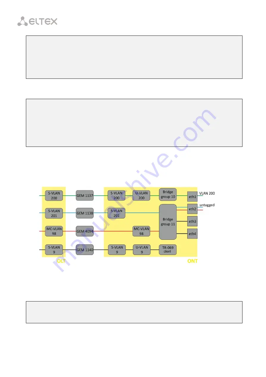
Configure the Internet (PPPoE), IPTV unicast, and management services via the TR-069 protocol. Set
the VLAN ID to 200 for Internet, to 201 for UC_IPTV. Set U-VLAN to 200 for Internet. Multicast traffic will
be transmitted to VLAN 98, management will be performed via VLAN 9.
Fig. 28.6 – Bridged Service Abstract Representation for Model 3
Step 1.
Create an Internet cross-connect profile to configure PPPoE in the bridge. Configure the
bridged service specifying the bridge group the ONT port will be connected to (in this case, it is equal to
10 for the first service).
LTP-8X(config)# profile cross-connect Internet
LTP-8X(config-cross-connect)("Internet")# bridge
LTP-8X(config-cross-connect)("Internet")# bridge group 10
Step 2.
To assign an S-VLAN, use the outer vid 200 command. The LAN port of the ONT will send
tagged traffic. To enable this, set U-VLAN equal to S-VLAN:
Содержание LTP-4X
Страница 1: ...1 Optical Line Terminals LTP 8X LTP 4X Operation Manual Firmware version 3 30 0 Issue 9 30 11 2017 ...
Страница 11: ...11 Part I General ...
Страница 29: ...29 Part II Getting Started with the Terminal ...
Страница 37: ...37 Part III Configuring the Terminal ...
Страница 98: ...98 Part IV ONT Configuration ...
Страница 174: ...174 Part V Terminal Monitoring ...
Страница 189: ...189 Part VI Terminal Maintenance ...
Страница 191: ...191 Step 2 Remove the module from the slot Fig 43 4 Removing SFP Transceivers ...


