


97
To remove the control panel:
1. Disconnect power from the range.
2. Remove the back panel from the backguard.
3. Remove the knobs.
4. Disconnect the infinite switches.
5. Disconnect the electronic oven control.
6. Disconnect the indicator light and the oven light
switch.
7. Remove two square drive screws from the back top
corners.
Corner screws
8. Remove two phillips screws, one in each corner of
lower front. Roll the bottom of the control panel out
and lift up.
Front corner screw
To remove the end cap:
1. Disconnect power from the range and remove the
control panel.
2. Remove the two screws holding the end cap to the
bodyside.
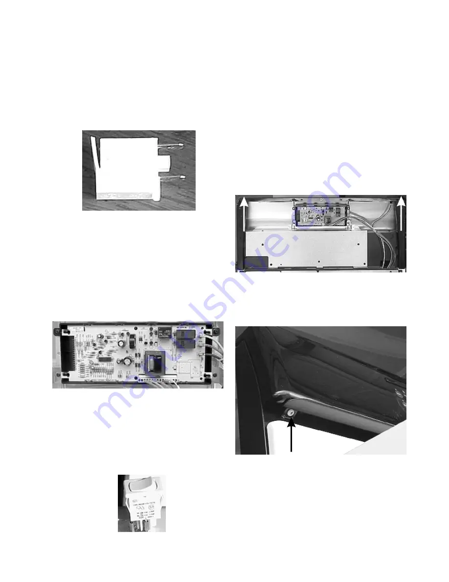
To remove the indicator light:
1. Disconnect power from the range.
2. Remove the back panel from the backguard.
3. Disconnect the wires from the light.
4. Push in and down.
Indicator light
To remove the electronic oven control:
1. Disconnect power from the range.
2. Remove the back panel from the backguard.
3. Disconnect wires and harness from the control board.
4. Remove the four screws. (One from each corner.)
Electronic oven control
To remove the oven light switch:
1. Disconnect power from the range and remove the
back panel from the backguard.
2. Disconnect the wires from the switch, squeeze the
sides, and push up.
Oven light switch
s
Содержание 30" GAS FREESTANDING RANGES
Страница 43: ...43 SAMPLE SCHEMATIC FOR ES100 CONTROL SYSTEM ...
Страница 50: ...50 SAMPLE SCHEMATIC FOR ES 200 CONTROL SYSTEM ...
Страница 60: ...60 SAMPLE SCHEMATIC FOR ES 300 CONTROL SYSTEM ...
Страница 72: ...72 SAMPLE SCHEMATIC FOR ES 400 CONTROL SYSTEM ...
Страница 84: ...84 SAMPLE SCHEMATIC FOR ES 450 CONTROL SYSTEM ...
Страница 93: ...93 Sample schematic for 36 gas range ...
Страница 130: ...130 NOTES ...
Страница 131: ...131 NOTES ...
Страница 132: ...132 ...


