


100
4. Disconnect the red lead from the spark module and
use the disconnect in the harness to disconnect the
black lead.
Removing the top burner valves:
1. Disconnect electrical power and turn the gas supply
off.
2. Remove the main top, manifold panel and burner
pan.
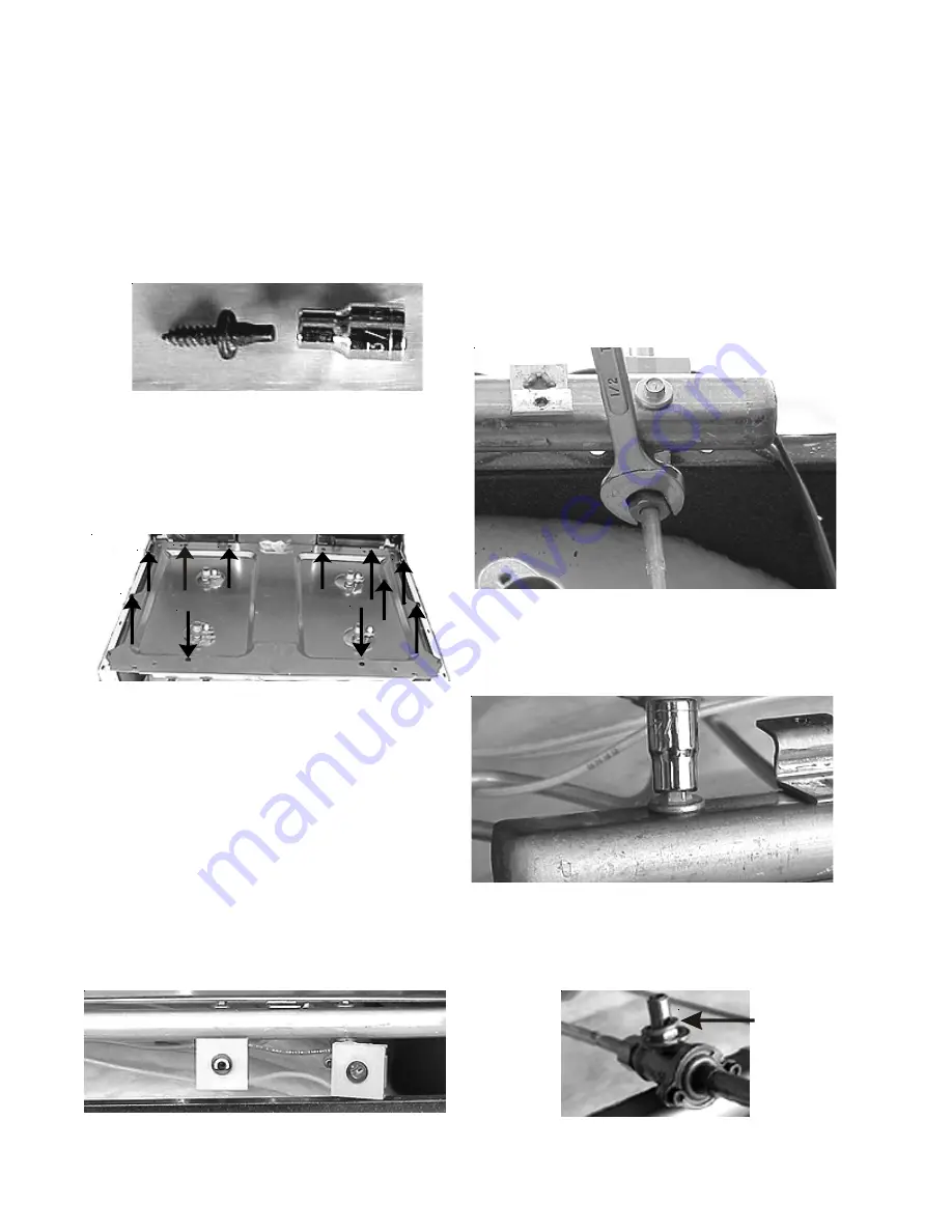
3. Using a 1/2” wrench disconnect the burner tubing
from the valve.
Disconnecting burner tubing
4. Remove the bolt holding valve to the manifold
with a 1/4” socket.
Valve bolt
Note:
When reinstalling the valve besure the gasket
between the valve and manifold is in place.
Valve mounting gasket
Removing burner pan:
1. Disconnect electrical power and turn the gas supply
off.
2. Remove the main top and manifold panel.
3. Remove the two main top locater pins using a 3/16”
socket.
Locator pin and 3/16” socket
4. Remove the eleven screws holding the burner box to
the manifold pipe, the bodysides, and back flange.
Burner pan screws
5. Lift the burner pan up and off.
Removing the top burner igniter switches:
Note:
The four switches and the harness are an
assembly and are changed as an assembly.
1. Disconnect electrical power.
2. Remove the manifold panel and burner pan.
3. Pull the switches off the shafts of the valves.
Igniter switches
s
s
Содержание 30" GAS FREESTANDING RANGES
Страница 43: ...43 SAMPLE SCHEMATIC FOR ES100 CONTROL SYSTEM ...
Страница 50: ...50 SAMPLE SCHEMATIC FOR ES 200 CONTROL SYSTEM ...
Страница 60: ...60 SAMPLE SCHEMATIC FOR ES 300 CONTROL SYSTEM ...
Страница 72: ...72 SAMPLE SCHEMATIC FOR ES 400 CONTROL SYSTEM ...
Страница 84: ...84 SAMPLE SCHEMATIC FOR ES 450 CONTROL SYSTEM ...
Страница 93: ...93 Sample schematic for 36 gas range ...
Страница 130: ...130 NOTES ...
Страница 131: ...131 NOTES ...
Страница 132: ...132 ...


