


SW37
Manual Step
SPST (ON)-OFF
SW36
Bus 1 Load
SPST ON-OFF
SW33
Bus 1 Merge
SPST ON-OFF
SW34
Bus 2 Merge
SPST ON-OFF
1 2 3 4 5 6 7 8
P103
Digital Board J3
Cathode
Anode
D21
Clock
Red LED
SW35
Bus 3 Merge
SPST ON-OFF
SW32
Stage 16
SPDT
ON-OFF-ON
SW31
Stage 15
SPDT
ON-OFF-ON
SW30
Stage 14
SPDT
ON-OFF-ON
SW29
Stage 13
SPDT
ON-OFF-ON
SW28
Stage 12
SPDT
ON-OFF-ON
SW27
Stage 11
SPDT
ON-OFF-ON
SW26
Stage 10
SPDT
ON-OFF-ON
SW25
Stage 9
SPDT
ON-OFF-ON
SW24
Stage 8
SPDT
ON-OFF-ON
SW23
Stage 7
SPDT
ON-OFF-ON
SW22
Stage 6
SPDT
ON-OFF-ON
SW21
Stage 5
SPDT
ON-OFF-ON
SW20
Stage 4
SPDT
ON-OFF-ON
SW19
Stage 3
SPDT
ON-OFF-ON
SW18
Stage 2
SPDT
ON-OFF-ON
SW17
Stage 1
SPDT
ON-OFF-ON
Gate Bus Switches
Bus 1
Bus 3
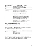
Figure 6-13: P103 Connections
A Note About P103 (Digital Board J3) Connections
You’ll notice that pin 1 of P103 connects to the common connection of Bus 3, which
should have been wired up when the panel strap connections were installed. The same is
true of pin 5, which connects to the common connection of Bus 1. This diagram
illustrates the connection if your gate bus switches choose Gate Bus 1 when the switch
lever is pointed up, and Gate Bus 3 when the switch lever is pointed down.
If, for some reason, your panel legend is reversed (lever up is Gate Bus 3 and lever down
is Gate Bus 1) simply reverse those connections to match.
62