


1 2 3 4 5 6 7 8
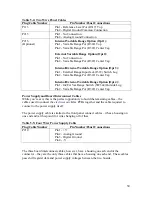
P209
Analogue Board J9
7
8
6
5
4
3
2
1
SW43
Range Select
SP8T
Rotary
Figure 6-12: P209 Rotary Switch Connections
Rotary Switch Notes
The rotary Range Select Switch wiring diagram most likely does not reflect the choice
you have made for your rotary switch. Generally, if you’re like the rest of most of the
known universe, you purchased a twelve position rotary switch and had to configure it so
that it would turn through only eight positions. So, on the back of your switch, there are
probably twelve pins around the outside of the switch, and one pin in the middle, instead
of the eight pins around the outside of the switch shown here.
That is, of course, fine. Just remember, like everything else in Bizarro Rear Panel World,
the pin assignments will work backwards. Make sure you verify which pins are selected
(shorted to the center “pole” pin) with each position.
As a reminder - nothing is connected to the pin that is selected in position 1 of the rotary
switch. A good way to remember it is pin 1 of the plug connects to the center pole
connection, and pins 2 through 8 connect to switch pins of the same number.
61