


Various and Sundry Strap Connections
You’re getting very close to the end of the panel strapping process, so hang in there. The
next set of connections consists of a few “single” connections – lines to connect jacks to
pots and switches, mainly. Also, some of the optional Variable Range Option
connections will be discussed, should you have decided to include that option.
o
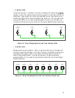
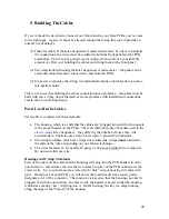
Random Signal Input Jack to Random Level Pot
Of course, this requires that you be absolutely sure which lug of your Random Signal
Input Jack is the “Tip” connection. If you use banana jacks, you are permitted to
smile smugly to yourself in appreciation of the fact that, for a banana jack, this is a
no-brainer – there is only one connection to a banana jack, and this the one
connection you need here.
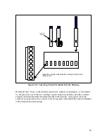
Solder a wire between the “tip” lug (or your single banana jack connection) of the
Random Signal Input Jack to the left most lug of the Random Level Pot, as viewed
from the back.
J14
Random Signal
Input
Ground
Lug
Back
of
Pot
Tip
Lug
R18
Random Signal
Level
Figure 4-10: Wiring the Random Input to the Random Level Pot
o
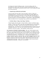
Clock Signal Input Jack to Clock Enable Switch
With no comment from the banana jack gallery, ensure that you know which lug of
your Clock Signal Input Jack is the “tip” connection, and solder a wire from it to one
of the lugs on the back of the Clock Enable Switch. Obviously, the Clock Enable
Switch is an SPST ON-OFF switch, so it doesn’t matter which lug you solder to here
– just (as usual) make sure you have the orientation of the switch correct to match
your panel legend.
34